


Optimizing the 4 Square Antenna for Enhanced Performance

Updated: Aug 31
The Four (4) Square antenna is a well-known DX design among amateur radio enthusiasts for its reliable performance and directional capabilities. When this 160 meter antenna is hung off one of K0UO’s 195-foot towers, and paired with four elevated quarter-wave radials on each vertical element, it offers a unique opportunity to improve efficiency and signal quality. This setup, also used by ON4UN/SK & K3LR in the past, combines the benefits of the standard 4 Square with the advantages of elevated radials, creating a system that stands out in both gain and and bandwidth.
This article explores how to optimize the 4 Square antenna without building four individual towers, and using elevated radials for better gain, detailing the design principles, installation tips, and performance benefits. Whether you are a seasoned ham operator or a dedicated antenna builder, understanding these elements will help you get the most from your HF low band antenna system.

There are a ton of YouTube videos that you can watch about this array, or pages of models; However, this is a real-world factual use and overview that has been rigorously tested on a large outdoor range situated in the far field.
At present, most HF amateur radio antennas, along with a large number of commercial HF arrays, have not been subjected to rigorous testing on antenna test ranges. This lack of formal testing raises important questions about the performance and reliability of these antennas in real-world conditions. Many amateur radio enthusiasts rely on specifications and marketing claims made by manufacturers, but without empirical data from controlled tests, these claims can often be misleading or overly optimistic.
Informal testing has been conducted on many VHF and higher frequency band antennas, thanks to organizations like The Central States VHF Society and Microwave Update. These dedicated groups have established amateur test ranges at their annual conferences, providing a platform for hobbyists and professionals alike to evaluate antenna performance. These events are invaluable as they not only foster community engagement but also uncover shortcomings in some manufacturers' models and their associated claims. Participants can share insights, compare results, and collectively improve their understanding of antenna design and performance.
However, despite the advancements in testing practices for VHF and UHF antennas, there remains a glaring gap in the realm of HF antennas. The absence of comprehensive real-world far-field testing for HF antennas, is a significant oversight in the amateur radio community. This lack of testing means that many users may purchase antennas based on incomplete or exaggerated performance data, which can lead to frustration and disappointment when the antennas do not perform as expected in actual operating conditions. As a result, much of the manufacturers' documentation might mislead consumers, creating a cycle of misinformation that affects both new and experienced operators alike.
It is important to note that not many antenna ranges even conduct tests on a 160-meter full-size antenna in the far field, specifically at distances of 3 to 10 wavelengths away from the antenna. This level of testing is critical for understanding the real performance characteristics of these large HF antennas in practical applications. In fact, it is likely that very few, if any, facilities have undertaken such comprehensive testing, including ground losses and soil connectivity differences.
The K0UO RSI Corp Test range has made significant strides in this area, providing valuable data and insights. This overview focuses on those specific antennas that are actively utilized on a daily basis by K0UO, highlighting their effectiveness and reliability in real-world scenarios.
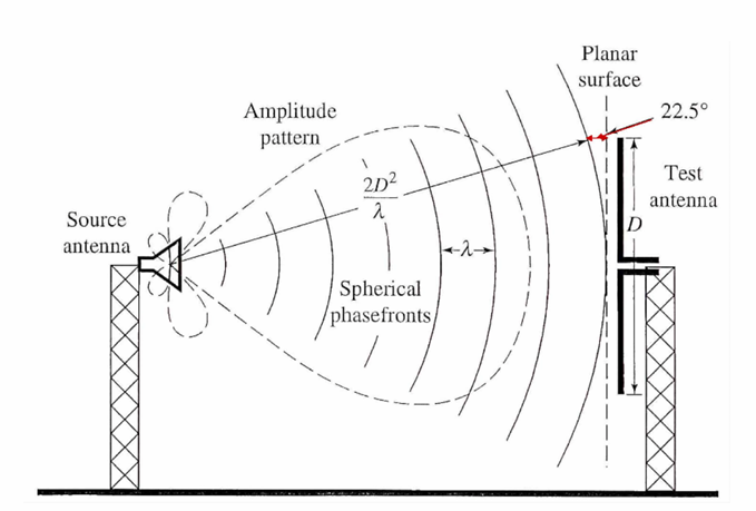
Testing antennas in the far field is crucial because it allows for the evaluation of how antennas perform when they are deployed in environments that mimic actual usage conditions. The far field is defined as the region where the distance from the antenna is sufficiently far enough that the radio waves have spread out and are essentially plane waves. This is particularly important for antennas that operate on lower frequencies, such as those in the 160-meter band, where the physical size of the antenna can be quite large compared to the wavelengths being transmitted. The K0UO RSI Corp Test range has established protocols to ensure that their testing accurately reflects these conditions, which can significantly affect the antenna's radiation pattern, gain, and overall efficiency.
Moreover, the implications of such testing are profound for amateur radio operators and professionals alike. By understanding how these antennas behave in the far field, users can make informed decisions about their antenna setups, optimizing their configurations for better signal strength and clarity. The data collected from these tests not only helps in validating the theoretical models presented in various online videos and articles but also provides a tangible benchmark for performance that can be relied upon in practical applications.

In summary, while there are numerous resources available online, including countless YouTube videos and theoretical models, the real-world testing conducted by K0UO's team at their RSI Corp Test range offers a unique and invaluable perspective. This testing is not only a testament to the capabilities of the antennas used, but also serves as a crucial resource for anyone looking to deepen their understanding of HF antenna performance in practical settings.
Understanding the 4 Square Antenna
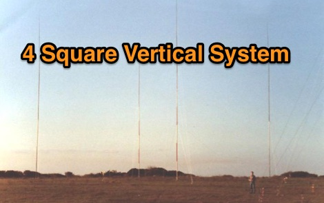
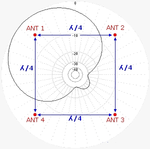
The standard Four (4) Square antenna is a directional array consisting of four vertical elements arranged in a square. Each vertical is typically a quarter wavelength long, and the array is fed in a way that produces a strong directional pattern with good front-to-back ratio and gain.
Note, K0UO blog uses dB gain, not dBi when providing antenna gain data.
Key Features of the a standard 4 Square
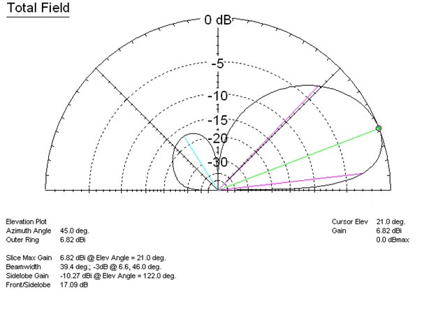
Directional gain: The square layout focuses energy in a preferred direction, improving signal strength. Typical Forward Gain: The forward gain is generally in the range of 4.2 to 5 dB.
Switchable Directions: The antenna provides full 360-degree coverage by switching the main beam to one of four directions, centered on the corners of the square (e.g., NE, SE, SW, NW).
Front-to-Back (F/B) Ratio:The front-to-back ratio indicates the antenna's ability to reject signals coming from the opposite direction of the main beam, which is crucial for reducing noise and interference 20db to 25db with good S/N
Takeoff angel: 15 to 25 degrees
Beamwidth: A diagonally firing quarter-wave 4-Square array typically has a half-power beamwidth 3dB of approximately 90 deg, providing broad coverage within each switched quadrant. Other sources cite a beamwidth of around 60 deg or 45 deg for some optimized designs.
Compact footprint: Compared to larger beam antennas, the Type 4 Square fits into smaller spaces.
Simple construction: The design uses vertical elements and a straightforward feed system, making it accessible for many operators.
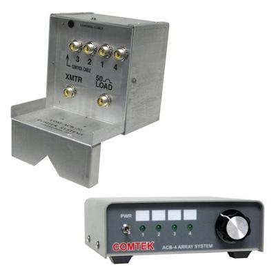
Directional Phasing Network: control is by phasing (K0UO uses Comtek or DXE phasing boxes) or build your own. Equal currents must be forced in all elements with exact phase relationships 0 back,+90 sides, +180 front, relative to a center node. Hybrid couplers are commonly used for this purpose and are band-specific. A conventional four-square to provide eight directions of fire instead of the normal four. This another four directions are located at points which are mid-way between the existing four. Total of eight selectable beam-headings spaces 45deg apart. see at
Fast Direction change: By fast switching relay controls.
The performance of the 4-Square antenna system is heavily dependent on precise phasing and a low-loss ground system. An extensive ground radial system for each element is critical for high efficiency and optimum gain for ground mounted systems., Which is very time consuming, and thousands of feet of copper wire is expensive.
The Role of Elevated Quarter-Wave Radials
K0UO had standard 4 squares on 160 to 40 meters to start, using Rohn towers and the extensive gound radial system as required. That system had to be moved, so it was time for improvements.
When supported and suspended from a single tower, like K0UO’s 195-foot structure, (where he has both a 160 meter and 80 meter 4 square array wires on one tower), the antenna gains more efficiency due to the increased height, which also lowers the takeoff angle while reducing ground losses. The tower is a 195 foot Rohn J 19 !/2" face tower an export type RIGID TUBE model, with four-way guying, where the top guy wires are cut for 160 meter. The lower feed-point is an elevated 20-foot high, 12-inch pipe support anchor for each of the four guys.

Elevated radials are horizontal wires or rods placed above the ground, typically a quarter wavelength long. In this setup, four elevated radials are attached to each vertical element of the antenna.
Why Use Elevated Radials?
Improved efficiency: Elevated radials reduce ground losses compared to ground-mounted radials or a ground plane.
Better bandwidth: The antenna system maintains a stable impedance over a wider frequency range.
Reduced noise: Elevating radials can help reduce noise pickup from the ground and nearby objects.
ON4UN & K3LR’s past use of elevated radials with a similar antenna design demonstrated measurable improvements in signal clarity and strength, which validates this approach. There has be some good presentations at many conferences over the years

Patterns models and Hardware links are listed at the end of this blog,
We will not going to be reviewing numerous model pattern pages; instead, this is an overview of a proven design that saves you a considerable time, money, and performs better than a standard array.
Installation Considerations for Elevated Radials
Proper installation is crucial to maximize the benefits of elevated radials. Here are some practical tips:
Radial Length and Placement
Each radial should be approximately a quarter wavelength long at the operating frequency.
The four radials on each should be evenly spaced around the base of each vertical element, ideally at 90-degree intervals. However using two each is only a .25 dB loss.
Elevate radials at least 10 to 20 feet or more above ground to reduce ground interaction.
Material and Support
Use low-loss wire or tubing for radials to minimize resistive losses.
Support radials with non-conductive materials such as fiberglass poles or insulated brackets.
Ensure radials are taut and free from sagging to maintain consistent electrical length.
Feedpoint and Matching
The feed system should be designed to accommodate the elevated radials, which affect the antenna’s impedance.
Use an antenna analyzer to fine-tune the feedpoint matching network for the best SWR (Standing Wave Ratio).
Consider using a balun or choke to reduce unwanted currents on feed lines.
Use a Hybrid coupler which are commonly used for this purpose and are band-specific.
Quarter-Wave Feedlines: Using 75-ohm 50-ohm coaxial cable exactly 1/4 wavelength long (adjusted for velocity factor) is essential for 'current forcing' to ensure equal currents, despite variations in input impedance caused by mutual coupling.

Performance Benefits Observed
Operators using the K0UO 4 Square antenna with elevated radials report several advantages:
Increased gain: The antenna exhibits gain improvements of up to 1 to 2 dB compared to ground-mounted radials.
Improved front-to-back ratio: Directionality sharpens, reducing interference from unwanted directions. (24dB F/B) using a good Hybrid coupler
Wider bandwidth: The antenna maintains a low SWR over a broader frequency range, reducing the need for retuning.
Lower noise floor: Elevated radials help reduce local noise, improving signal-to-noise ratio S/N on receive, less QSB noted, in fact most of the time K0UO does not even need his long beverage antennas. Dramatically reducing local interference on the lower HF bands noise from behind the selected direction. Note:This receive improvement is often more practically valuable than the forward gain.
Improved efficiency: Elevated radials reduce ground losses compared to ground-mounted radials or a ground plane and cleans up the pattern.
Lower cost: Most hams use Rohn towers for the antenna on 160 and 80 meters, with the K0UO system only one tall support is need not four.
Easy to install: For ground-mounted systems, having a comprehensive ground radial system for each element is essential for achieving high efficiency and optimal gain. This process is very time-consuming and labor-intensive, and it requires thousands of feet of copper wire, which can be costly.
These benefits translate into clearer contacts, longer-distance DX communications, and more reliable operation during contests or DXing.
Practical Example: K0UO’s 195-Foot Tower Setup
K0UO’s tower provides an excellent platform for the 4 Square antenna with out building four individual towers. The height allows the antenna to clear nearby obstructions and take advantage of the elevated radials’ efficiency.
Setup Highlights
Four vertical elements arranged in a square, each with four elevated radials.
Radials elevated approximately 12 feet of more above ground.
Feed system optimized with an antenna analyzer for minimal SWR.
Use of quality coaxial cable and balun to maintain signal integrity.
Control phasing unit and antenna patterns https://static.dxengineering.com/global/images/instructions/com-acb-160-a.pdf
This setup has demonstrated consistent performance improvements in both local and DX contacts, confirming the value of combining the 4 Square with elevated radials.
Maintenance and Troubleshooting Tips
To keep the antenna system performing at its best, regular maintenance is essential.
Inspect radials and supports: Check for corrosion, breaks, or sagging wires.
Verify feedline integrity: Look for damage or water ingress in coaxial cables.
Monitor SWR regularly: Use an antenna analyzer to detect changes in antenna tuning.
Check for interference: Elevated radials can sometimes pick up unwanted signals; adjust placement if necessary.
Addressing these issues promptly helps maintain optimal antenna performance over time.
Currently, the majority of HF amateur radio antennas, as well as a significant portion of commercial HF beams, have not undergone testing on antenna test ranges.
Many VHF and higher frequency band antennas have been subject to informal testing, facilitated by organizations such as The Central States VHF Society and Microwave Update. These groups annually establish amateur test ranges at their conferences, which is beneficial as it reveals deficiencies in some manufacturers' models and claims.
However, there is a complete lack of real-world far-field testing for HF antennas, including wire-based Hex-Beams and high-performance Yagi beams. Consequently, much of the manufacturers' documentation may be misleading to consumers.
Steve Walz, K0UO: "I started with calculators, and some of us are old enough to remember using slide rules and pencils, before moving to computer modeling. It's astonishing to see how far we've come, and in a few more years, like it or not AI will further revolutionize antenna design".
"After designing an antenna, we now have the advantage of using our outdoor testing range to validate the results."
"I consider it essential to confirm results and assess performance in real-world conditions. My team has collaborated with a number of commercial and DOD clients to do just that."
Summary
Using the 4 Square antenna with four elevated quarter-wave radials on each vertical, as demonstrated on K0UO’s 195-foot tower and outlined in ON4UN in his Low Band DXing Book and K3LR, offers clear performance advantages. Elevated radials improve efficiency, bandwidth, and noise reduction, making the antenna more effective for long-distance and contest communications.
For amateur radio operators looking to enhance their antenna systems, this approach provides a practical and proven method to boost signal quality without requiring complex or expensive equipment. Careful installation, tuning, and maintenance will ensure the antenna delivers strong, reliable performance for years to come.
Consider evaluating your current antenna setup and explore how adding elevated radials to a 4 Square array could improve your station’s capabilities. Experimentation and measurement are key to unlocking the full potential of this classic antenna design.
Best model
ON4UN/SK in his book "Low Band DXing" has all the models
Elevated Radials
For Patterns and Hardware see


Comments