


K0UO Outdoor Antenna Test Range Facility for Measurement Testing in the Far Field "Antenna University"

Updated: 5 days ago


At the RSI Corp & K0UO rhombic farm and antenna test range, the world’s largest facility dedicated to advanced HF wire antenna design and testing, where engineers can push the boundaries of what’s possible. We don’t just guess antenna gain - we measure it meticulously, ensuring every antenna performs at its peak. The RSI Corp antenna Far Field Test Range uses advanced RF measurement to confirm all the antenna preformance.
Even with high-precision electromagnetic modeling software such as NEC-2, NEC-4,AN-SOF or HFSS, which are widely recognized for their capabilities in simulating antenna behavior and performance, it is essential to understand that computer simulations are fundamentally based on idealized mathematical conditions. These software tools utilize complex algorithms and theoretical models to predict how antennas will behave under various conditions, but they often operate under assumptions that may not fully capture the intricacies of real-world environments. For instance, while these simulations can provide valuable insights into parameters such as gain, radiation patterns, and impedance, they typically do not account for all the variables present in practical scenarios. Factors such as nearby structures, ground conductivity, atmospheric conditions, and even the presence of human bodies can significantly influence antenna performance. These elements introduce complexities that mathematical models may simplify or overlook entirely.
Importance of Far-Field Testing
Real-world far-field testing, therefore, remains the gold standard for validating antenna designs and performance characteristics. This type of testing involves measuring the actual electromagnetic fields produced by an antenna at a considerable distance from the source, where the effects of the antenna's physical structure and the surrounding environment can be accurately assessed. During these tests, antennas are placed in an open area, often referred to as an anechoic chamber or a far-field test range, where external noise and reflections are minimized.
Environmental Variables
One of the primary advantages of far-field testing is its ability to account for environmental variables that can impact antenna performance. For example, the presence of nearby buildings can cause multipath propagation, leading to interference and distortion in the signal. Additionally, atmospheric conditions such as humidity, temperature, and precipitation can affect the propagation of radio waves, altering the effective range and reliability of the antenna. By conducting far-field tests, engineers can gather empirical data that reflects these real-world conditions, providing a more accurate representation of how the antenna will perform in its intended application.
Physical Interactions
Moreover, far-field testing allows for the observation of physical interactions that modeling software may not fully replicate. For instance, the interaction between the antenna and the ground can have significant effects on radiation patterns and efficiency. Ground reflection, absorption, and scattering are all phenomena that can alter the expected performance of an antenna, and these factors are best understood through empirical measurement rather than theoretical prediction.
Conclusion
In conclusion, while high-precision electromagnetic modeling software serves as an invaluable tool in the design and analysis of antennas, it is crucial to complement these simulations with real-world far-field testing. This combination of theoretical modeling and practical validation ensures that antenna designs are not only theoretically sound but also robust and reliable in actual operational environments. By bridging the gap between simulation and reality, engineers can achieve a higher level of confidence in their antenna designs, ultimately leading to better performance and functionality in the field.
predict.
The K0UO Antenna Test Facility (ATF) far-field range site and 4KS Walz airport offers a real-world learning environment in Kansas for STEM antenna projects. If your school or University has a research STEM program for antennas or aerospace, contact me. Building and experimenting can aid learning and development. An ISR, EME, RFI and RF test site by RSI Corp of Kiowa KS, this test range is Department of Defense compliant.
Test range: For ISR equipment testing is extending several miles to the west and north of 4KS Walz Airport, for ISR, EME, RFI, and RF test site number 2, by RSI Corp. This is part of Vance AFB 1D MOA DAF Proposed Action, which has been approved, to acquire new airspace that allows the 71 FTW and other groups to schedule autonomously, and ensures nearby access to airspace needed for low-altitude non-hazardous flight training and equipment testing.
The site emphasizes the scientific method: model → build → far-field test → refine

Known as "The K0UO & RSI Corp Antenna University" The test range is a controlled testing environment used to measure and evaluate the performance of equipment, and antennas in the Fraunhofer zone (Far Field), and is an accredited wireless outdoor testing range laboratory site, using drones at the on site "4KS" airport. UAS Infrastructure
ground-based radar systems, Automatic Dependent Surveillance-Broadcast (ADS-B), with a network of ADS-B receivers to promote safe operations in the airspace.
The K0UO & RSI Corp platform, which uses Artificial Intelligence to design traveling wave and other antennas, is much more reliable, and completes the process in about 5% of the time required by traditional modeling programs. Setting it up requires time, similar to the initial setup of the original computer modeling software. It's easy to make mistakes by assuming artificial intelligence can operate without errors.
The facility is at the forefront of this movement, testing antennas that integrate AI for both amateur and commercial use. These antennas are designed to handle complex propagation conditions and interference, making them ideal for DoD, High-frequency stock trading groups, and broadcasters who demand the highest reliability.
Steve Walz, K0UO: "I started with calculators, and some of us are old enough to remember using slide rules and pencils, before moving to computer modeling. It's astonishing to see how far we've come, and in a few more years, like it or not AI will further revolutionize antenna design".
After designing an antenna, we now have the advantage of using our outdoor testing range to validate the results.
"I consider it essential to confirm results and assess performance in real-world conditions. My team has collaborated with a number of commercial and DOD clients to do just that."
Efficiency, Flexibility, Reliability
Measuring the simulated RF radiation pattern equipment and antenna is essential to understand its performance at your location, involving crucial steps for precise assessment and analysis.

The scientific method serves as the foundation for all EMC/EME, RFI, RFR antenna pattern testing activities at the K0UO test range. All surveys and tests must first be subjected to the rigorous processes of the scientific method.
Modern programs using NEC2/NEC4, AN-SOF and Scilab model RF absorption in the ground (Electrical Conductivity) under antennas with the Sommerfeld-Norton ground model. Older models inadequately address loss and ground reflections at low angles. Skywave signals form through antenna-ground interactions within 1 to 5 wavelengths in the Fraunhofer zone (Far Field). Ground losses affect some antennas more than others, and surrounding objects like buildings, trees, and fences in the near field also significantly impact performance, which models may not accurately depict.
Real-world patterns might not align with theoretical models, unless you've tested the ground electrical conductivity and the model incorporates that data.
"You can’t talk about antenna gain measurement without giving a shout-out to the RSI Corp/K0UO outdoor antenna test range. This place is legendary in the ham radio and commercial HF world. It’s the largest facility dedicated to advanced antenna design and testing." DoD Contractor
All antennas are modeled using NEC5 and HFTA (High Frequency Terrain Analysis) to evaluate the take of angle of the various antennas over real ground.
A word about modeling: You no longer need the latest modeling software, as it's design is rapidly evolving with Artificial Intelligence.
We started integrating AI with modeling in 2024, and now have developed an AI analysis platform focused on antenna performance and specific parameters. Be cautious and invest time in setting the correct parameters for your "AI platform".
One high end paid AI platform is now using AN-SOF and Scilab model, which is a robust simulation engine designed for the modeling and analysis of complex antenna systems and radiating structures.
Gain total spatial awareness of your antenna’s performance with immersive 3D rendering. AN-3D Pattern utilizes colored mesh and surface mapping to visualize radiation lobes with professional clarity.
Creating a well-designed platform using scientific and engineering knowledge is crucial.
Relying solely on ChatGPT is not the solution at all!

Key Reasons Far-Field Testing Is Essential Beyond Modeling
1. Inhomogeneous Ground & Real-World Soil Effects
Modeling Constraints: Antenna modeling software generally assumes a uniform, flat ground plane with fixed values for conductivity and permittivity.
Real-World Conditions: Actual ground composition varies significantly over large areas, changes dynamically with moisture and weather conditions, and may include underground mineral deposits or water tables. Since wire arrays depend heavily on ground reflections (or ground-return paths for vertical polarization), far-field measurements are crucial to understanding how actual local ground characteristics affect elevation patterns and gain.
2. Physical & Mechanical Tolerances
Modeling Constraints: Models assume perfectly straight wires, precise element angles, uniform wire tension, and exact spacing.
Real-World Conditions: In practice, wire antennas are subject to sag, thermal expansion, mechanical stress, interference from surrounding vegetation, and slight structural deviations on support masts or towers. Far-field measurements provide an accurate representation of the combined radiation pattern resulting from these inevitable physical imperfections.
3. Near-Field Environmental Coupling
Modeling Constraints: Accurately modeling every adjacent object—such as neighboring towers, guy wires, power lines, fences, surrounding buildings, or nearby trees—requires substantial computing power and precise 3D modeling of each structure's material properties.
Real-World Conditions: Unintended reradiation or inductive coupling from nearby metallic structures can significantly alter far-field main lobes, fill in expected nulls, or distort side lobes. Far-field testing directly measures the cumulative impact of the entire operational environment.
4. Feed System & Component Losses
Modeling Constraints: Software typically calculates theoretical feed impedances and ideal currents, often simplifying component losses in transformers, baluns, common-mode choke currents, and coax/ladder-line feed systems.
Real-World Conditions: Far-field testing verifies actual radiated power efficiency and confirms whether feed-line radiation or phase mismatches are affecting directivity.
5. True Far-Field Distance Validation
Wavefront Planarity: An antenna's radiation pattern evolves as energy transitions from the reactive near-field to the radiating far-field. Far-field testing ensures that measurements are taken at a distance where the wavefront is essentially planar, accurately reflecting how the antenna will launch long-distance (DX) signals.

Simulations use algorithms to estimate antenna performance under conditions like frequency and polarization but can't account for real-world variables such as nearby structures and electromagnetic interference. After simulations, conduct field measurements of the RF radiation pattern. This involves using equipment like an RF field strength meter to gather data on the antenna's energy radiation in different directions.
Modeling Traveling-wave Arrays
AN-SOF offers higher simulation accuracy than legacy NEC software for large traveling-wave antennas like Rhombics and Beverages. Its advanced Conformal Method of Moments (CMoM) engine and Sommerfeld ground physics enhance performance. AN-SOF accurately simulates these antennas by calculating currents over the actual wire surface, unlike NEC's thin-wire approximation, which can lead to inaccuracies.
Exact Kernel vs. Thin-Wire Approximation
NEC Limitation: Relies on thin-wire approximation, causing non-physical current spikes near loads or transitions.
AN-SOF Advantage: Uses CMoM with an Exact Kernel for accurate current modeling over the wire's surface.
Apex Junction Stability
NEC Limitation: Struggles with acute angles, causing mathematical breakdowns.
AN-SOF Advantage: Handles acute angles without numerical instabilities.
Ground Physics & Near-Field Losses
NEC Limitation: Oversimplifies ground return currents using Reflection Coefficient Approximations.
AN-SOF Advantage: Uses the Sommerfeld-Wait ground model for accurate near-field calculations.
Importance of Far Field Testing in HF Traveling-Wave Arrays
Far Field testing is crucial for validating the performance and efficiency of HF Traveling-wave arrays. It measures electromagnetic fields at a distance, providing insights into radiation patterns and gain. This testing is essential for applications like military communications and broadcasting, ensuring optimal performance. Despite challenges in setup and data interpretation, Far Field testing remains indispensable for capturing real-world variables that simulations can't fully replicate.
Note: This K0UO blog uses dB gain, not dBi, for antenna gain data. K0UO is using AI, making it one of the most sophisticated amateur radio stations globally.

The K0UO amateur antenna range and testing site encompasses over 1,200 acres surrounding the main antennas and ranges. These areas are utilized through ownership, leased permissions, or deeded rights of way (ROW) for far-field measurements. The site runs parallel to the 4KS Walz airport, providing over 2,500 feet for one of the far-field ranges. This range employs a portable tower and drones equipped with standardized, calibrated RF, EME, and field strength survey instruments, which are used for Department of Defense, amateur radio, and commercial wireless telecommunication antennas. The K0UO is a highly technical facility dedicated to accurately measuring an antenna's performance characteristics, such as its radiation pattern and gain.
K0UO has significant real estate, so anechoic chambers are not needed, both Near field and Far field testing is conducted at this site in Kansas
Stand-alone towers: RSI Corp and K0UO/R has access to a series of dedicated stand-alone towers up to 500 feet tall (no other users on these towers) specifically designed for HF to MW operations as well as for far-field testing of antennas. These towers are uniquely positioned, standing tall and isolated in a very rural ranching setting, ensuring that no other antennas are mounted on them or interference . This strategic setup allows for optimal performance and minimal interference, making them ideal for serious professional projrcts. Think about how these towers could be uses by your group and project no of test rang site has this enique opportunity with unlimited possibilities. Located at a distance of up to 20 miles from the main 4KS airport RSI Corp site on the east side of the Kansas Red Gyp Hill ranching area, these towers are part of an extensive test range that facilitates a variety of radio frequency experiments and competitions. All can be connected with a private microwave internet point-to-point backbone network.
The towers are registered with the FCC Antenna Structure Registration (ASR) system. Several notable structures are listed, including the following:
#1,216,715 at a height of 59.5 meters on site,
#1,252,737 reaching 70.2 meters,
#1,252,738 towering at 89.6 meters,
#1,260,299 standing at 42.6 meters,
#1,314,639 at 88.4 meters,
#1,216,786 reaching a height of 97.5 meters,
#1,252,503 at 77.7 meters,
#1,235,485 at an impressive height of 149.4 meters dedicated to FM broadcasting,
and finally, ASR# 1,252,009 standing at 85.30 meters.
This is a very unique situation and an advantage on many projects requiring tall towers.
The data from these measurements is invaluable, allowing visualization of the radiation pattern in polar plots or 3D visualizations. This reveals the main lobes where the antenna is most effective and any nulls or reduced signal areas, crucial for optimizing coverage and minimizing interference in wireless communication. Additionally, measuring the RF radiation pattern can identify discrepancies between simulated results and actual performance due to factors like physical installation, nearby objects, and environmental variations. Understanding these differences is essential for refining antenna design and improving system performance.

Testing and survey test equipment with an analysis
Antenna gain is basically a measure of how well your antenna focuses energy in a particular direction compared to a standard reference antenna, usually an isotropic radiator (which radiates equally in all directions). Think of it like a flashlight beam - a narrow, focused beam shines farther and brighter than a wide, scattered glow.
Understand that most HF amateur radio Yagi beam antennas and a large portion of commercial HF beams have not been tested on antenna test ranges today.
Many VHF and higher band antennas have undergone some informal testing thanks to groups like The Central States VHF Society, Microwave Update, and others who annually set up amateur test ranges at their conferences. This is beneficial and highlights deficiencies in some manufacturers' models and claims.
However, there is a complete absence of real-world far-field testing for HF antennas, such as wire-based and high-performance Yagi beams. Much of the manufacturer's documentation can be quite misleading to consumers.
Why does this matter? Because in radio communication, focusing your signal means you can reach farther, cut through noise, and improve your overall signal quality. Whether you’re a ham radio operator trying to snag a rare DX contact or a broadcaster aiming for clear coverage, antenna gain is your secret weapon.
But here’s the kicker - the gain you think your antenna has, might not be the gain it actually delivers. That’s where antenna gain testing comes in. It’s the process of measuring your antenna’s real-world performance, so you know exactly what you’re working with.
In summary, the act of measuring the EMC/EME, RFI and RF radiation pattern and gain is not merely a technical requirement; it is a vital process that informs you about the antenna's real-world effectiveness and efficiency at your location. It bridges the gap between theoretical predictions and practical applications, ultimately leading to better system design, enhanced performance, and more reliable communication networks.

The primary purpose of an outdoor test range is to provide a dedicated and controlled area for the testing and evaluation of systems and technologies under realistic conditions. This is particularly crucial when laboratory simulations and indoor testing are insufficient to capture the complexities of real-world environments.
RF near and far field testing following many protocol like IEEE-299, MIL-STD-285, NSA 65-6, CTIA CATL certification testing along with: Probe symmetry and amplitude ripple measurements. RSI Staff has the required high Security Clearances for most projects.
RSI can do Technical writing to USAF T.O., DoD-DoW, Army TM, NAVAIR standards, Motorola, IEC 1082, and other commercial standards. Now working with groups on Trickster capabilities and ISR Decoy capabilities which enable maximum flexibility in any Agile Combat Employment scenario in interoperability and is Department of Defense compliant
ANSI/IEEE Std. 149-1979 1 MHz to 18GHz
EMF /EMI Testing (Electromagnetic Fields & Interference) Surveys in accordance with ICNIRP & CEMFAW Guidelines
Active Facility Clearance (FCL)
RSI Corp. ensures strict, continuous compliance with the National Industrial Security Program Operating Manual (NISPOM) regulations.
RSI Corp has active Classified contracts or has a documented, ongoing business need to access classified data.
RSI has a continuously employed designated Facility Security Officer (FSO) who holds a personal clearance at or above the level of the FCL
In addition to formal DCSA reviews, the company's FSO performs and documents comprehensive internal self-assessments at least annually.
The Test Range Site continuous monitoring protocols, tracking mechanisms, and security education awareness logs.
The sites objective is to always have Superior / Commendable status. Which is only Granted to pristine operations with zero critical issues, highly active security communities, and proactive vulnerability self-reporting
Partnerships with industry, government, tribal (like Choctaw Nation), and academia (like WSU), CReSIS to test airborne systems for Emerging Aviation Technology

The K0UO amateur ham radio and commercial antenna range Antenna Test Facility ATF, is in an electromagnetically-quiet area, and testing site has the use of over a 1200 acres around the main antennas for far field measurements, using a portable tower or drone loaded with calibrated RF, EME, power density, field strength, and non-ionizing radiation survey instruments, (also has been used for DOD DOW and Commercial measurements).

Antenna range testing is crucial for ensuring the efficiency, reliability, and even regulatory compliance of antenna systems. By providing precise performance measurements and reducing interference, antenna ranges contribute to the development of high quality antennas for modern communication networks. As technology evolves, these testing facilities will continue to be instrumental in enhancing connectivity and innovation across various industries. In fact we are using AI, which is now becoming an advanced tool in analyzing, developing, and expanding research in RF and antenna.
The following equipment is what my group, RSI will normally use to perform an EMC/EME, RFI, RF test assessment:
Signal generator for the test source
Vector or scalar network analyzers
Calibrated RF Meter
Calibrated E-Field Probe
Calibrated H-Field Probe
Calibrated Personal Protection Monitor
2 Meter “Story Pole”
Digital Camera
Special Film Camera
Sling Psychrometer
GPS/GNSS and magnetic locator
Tape measures, survey lasers using optical equipment, range poles, Trimble S3 with robotic function and 5000 meter range
Portable tower, and or drones with calibrated antennas and equipment
Real time data acquisition computer system for automated pattern measurement

Our Team in Action at a Telecom-site, Jon Walz "KD0DCO" of Concrete Walz & RSI Corp
Some equipment may have a limited frequency range or be very directional. Most RF probes used at communication sites are field dependent. At sites with transmitters below 300 MHz for EME/MPE testing, both the magnetic and electric fields must be measured, as either could be dominant. Additionally, the site may be assessed for induced and contact current hazards. An RF assessment or NIER Report at any RF site is complex and requires a trained, competent, and qualified assessor with extensive site knowledge and proper equipment.

How Signal Gain Measurement Works in Practice
Now, you might be wondering, “Okay, but how do you actually measure antenna gain?” Great question! The process can be surprisingly straightforward or quite complex, depending on your setup and accuracy needs.
Here’s the gist:
Reference antenna setup: You start with a known antenna whose gain is already established.
Test antenna placement: Place the antenna you want to test in the same position and orientation.
Signal transmission: Transmit a known signal from a source antenna.
Signal reception: Measure the received signal strength with both antennas.
Calculate gain: Compare the received power levels to determine the gain difference.
At K0UO, we use a massive open field with precise positioning systems and calibrated equipment to get ultra-accurate measurements.

One tip learned the hard way: make sure there’s minimal reflection and interference during testing. Nearby metal objects, buildings, or even the ground can mess with your readings. Using a turntable to rotate the antenna and plot the radiation pattern is also a game-changer.

The K0UO RSI Corp RF test range site can provide test aircraft that are Department of Defense compliant, fitted with an electro-optical, infrared EO/ISR sensor, operator mission, tactical radios, and data link a testing area at the 4KS Walz airport. TEST SITE @ https://maps.app.goo.gl/LQeAZCGkZxZ9D6Ky9

RSI Corp back in 2002 formed an educational alliance with NWOSU, RSI had offices and classrooms on the NWOSU Alva, OK campus, where we taught both University accredited, and Adult specialized RF, safety and agriculture courses. The NWOSU campus office was under the leadership of Gary Gerber "KB0HH", teaching courses like "Superior Survey Techniques SST (RF)", which follows a book of the same name, that I wrote in 1998. https://www.rsicorp.com/sst

RSI’S Radiofrequency Safety International Technical group has performed technical, safety, RF EME and EH&S general hazard inspection assessments at thousands of sites throughout the country, including many major broadcast sites, tower antenna farms, major buildings, and DoD installations. Radiofrequency Safety International and Steve Walz is using AI, which is now becoming an advanced tool in analyzing, developing, and expanding research.

Because EMC/EME, EMF, RFI, RFR is considered a physical hazard, proper programs must be in place to ensure safety at an RF test site. This is just like noise or air pollution. Everyone knows about and has noise and air sampling done; the same application applies to electromagnetic energy emissions. Testing must be done by a qualified EME/RF person.
Testing must be done by a qualified EMF, EMC/EME, RFI RF professional
Training must be done for workers who may be exposed to EME/RF above the uncontrolled levels so they can recognize and avoid the hazard
A Plan must be in place
The Rooftop Visual Audit™ will include:
Map of Rooftop layout including antennas and associated equipment areas showing both licensed and unlicensed occupants
Inventory of antennas including:
Operator (if information is available at the site)
Antenna type and MFG/Model as available
Photographs of all antennas and associated equipment areas

RSI Virtual University, exclusive online certification training program. See RSI Corp: Virtual University

Above: Mobile Radio Technology (MRT) magazine March 1997 cover page, depicting RSI Corp and Steve Walz's performing an RF Survey, with a complete article on the procedures 
Two of the taller steel towers in use at K0UO a 100 foot on the left and a 195 on the right with HF LPDA beams on top AI technologies are used to enhance the efficiency and accuracy of antenna design, quickly generate simulation results, and fine-tune antenna size and shape for improved performance and is an advanced tool in analyzing, developing, and expanding research in EMC/EME, RFI, RF and antennas.
I started with calculators, and some of us are old enough to remember using slide rules and pencils, before moving to computer modeling. It's astonishing to see how far we've come, and in a few more years, like it or not AI will further revolutionize antenna design.
Artificial Intelligence (AI) and Machine Learning (M/L) are revolutionizing how engineers analyze, design, and troubleshoot complex antenna radiation patterns. In traditional RF (Radio Frequency) engineering, evaluating massive setups—like multi-element wire arrays or phased arrays—requires staggering amounts of mathematical computation or weeks of field testing
AI bypasses these bottlenecks by automating pattern recognition and predicting electromagnetic behavior in real time we are using it now on the test range.

Layout out before testing
The assessment must be repeatable. The methods and procedures must be able to stand the scrutiny of a FCC, DoD, zoning board or city councils, as well as the possible scrutiny of a legal representative. My team uses industry standard procedures for environmental assessments, which have been able to stand the test of time.

This uncertainty term encompasses all non-repeatable errors stemming from the receiver, cables, temperature, variations in the AUT, and similar factors. It is anticipated that temperature fluctuations can be a factor at an outdoor range, and the source antenna might be affected by movement due to wind. Furthermore, scattering caused by the dynamic nature of the terrain and trees between the source and AUT is included in this term.
The best method is to estimate this quantity is by comparing the far-fields from two or more azimuthal scans conducted with identical scan parameters. Ideally, K0UO uses five or more repeat measurements are taken without altering the measurement system.
Then the far-field patterns of these repeat measurements are averaged, and this average is compared to a single measurement through complex plot subtraction. The pattern comparison and the RMS level are then utilized to determine the estimated uncertainty.

Conclusion
Antenna range testing is crucial for ensuring the efficiency, reliability, and regulatory compliance of antenna systems. By providing precise performance measurements and reducing interference, antenna ranges contribute to the development of high quality antennas for modern communication networks. As technology evolves, these testing facilities will continue to be instrumental in enhancing connectivity and innovation across various industries.
Antenna Gain: How well an antenna amplifies a signal in a particular direction.
Antenna Pattern: The 3D radiation pattern showing the directionality of the antenna.
Input Impedance
Frequency range
Polarization
Radiation Efficiency
Radiation Pattern
The Range Facilitates R&D and Innovation, Provides a dedicated environment for engineers, researchers and radio ham to develop and validate new antenna designs efficiently.

The best equipment on the market today can have as much as 4 dB of error. These items can in some cases be addressed and mitigated with proper training. Some of the other equipment could have as much as 30 dB of error in complicated environments.
The Rhombic antenna farm, which was engineered and built single handed, stands as a testament to advanced engineering and design in the field of telecommunications. This facility is not just a simple installation; it encompasses a sophisticated array of technologies and infrastructure that enable effective communication over vast distances. Among its most notable features are the massive Rhombic antennas and beverage antennas, both of which are designed for optimal performance in receiving and transmitting signals.

Testing the Onsite Rhombic Arrays
The Rhombic antennas, known for high gain and directivity, are positioned to optimize effectiveness across frequency ranges. Their geometric shape enables precise signal capture, ideal for long-distance communication. Beverage antennas, low-profile and used for receiving, excel with low-angle signals, enhancing distant transmission reception.
All antennas have been tested in the far field to assess performance and reach. These measurements evaluate signal strength and quality at various distances, allowing for optimization. This ensures the station operates efficiently and meets modern communication demands.
NOTE, Don't underestimate the performance of the Rhombic, unless you have
personally built and used one. The Rhombic antenna, known for its distinctive shape and design, is a remarkable piece of engineering that can significantly enhance radio communications. With their large size, Rhombic antennas utilize thousands of feet of wire, meticulously arranged to capture signals across various frequencies and angles. This extensive wire configuration enables the antenna to effectively gather radio waves that may be arriving from multiple directions, thereby reducing the effects of fading—a common issue in radio transmission that can lead to signal loss and degradation. The design of the Rhombic antenna allows it to function as a traveling wave antenna, which is particularly noteworthy. Unlike traditional antennas that may rely on standing waves, the traveling wave design facilitates the continuous propagation of signals along the length of the antenna. This characteristic contributes to a more stable and reliable transmission, making Rhombic antennas a preferred choice for many radio enthusiasts and professionals alike. Moreover, the advantages of Rhombic antennas are not easily captured through standard modeling techniques. While simulations and theoretical models can provide some insights, they often fail to account for the complex interactions and behaviors that occur in real-world scenarios. The unique properties of traveling wave antennas, such as their ability to maintain consistent performance over a broad bandwidth and their resilience to environmental factors, can only truly be appreciated through hands-on experience. In conclusion, the Rhombic antenna stands out as a powerful tool in the realm of radio communications. Its intricate design and large-scale construction allow it to excel where other antennas may falter, making it an essential consideration for those serious about optimizing their signal reception and transmission capabilities. Only through personal experimentation and utilization can one fully grasp the remarkable benefits that a Rhombic antenna can offer.
Check out this overview of the "Amplified Re-entrant Rhombic K0UO System" as used on a DoD project, which provided reliable and efficient HF communications for a circuit to Guam from the K0UO site in Kansas. see at https://www.k0uo.com/post/understanding-re-entrant-rhombic-array-antennas-design-features-and-applications

Modern alternatives still can't beat the big HF Rhombic:
Using the K0UO +90% re-entrant re-phasing system, no power is lost by terminating resistors.
Yagis even stacked ones,( 4 over 4 over 4 at 200 feet have about the same gain)
Log-periodic antennas
Vertical phase arrays, 4 Sqs
Wire antennas with tuners
Phased dipoles
The Best Antenna is one that is "In the Air and On the Air"! As any good antenna experimenter knows, the more antennas the better, that way you can test and see how they are really working. You won't know you have a good antenna if you can't compare it with others!

The K0UO RSI Corp Antenna Test Facility ATF near Kiowa, KS, is in an electromagnetically-quiet area.

The range is in a very rural area, near the center of the United States, the integrity of the test results have no RFI the from external interference.
Massive scale: The range is known for its size and extensive collection of antennas, and towers, which is rare for an individual operator.
Low interference: The remote, isolated location means the antennas are in an electromagnetically quiet environment, which is ideal for accurate and high-quality testing.
Extensive equipment: The facility houses in the aircraft hanger, many different types of antennas and equipment, used for a variety of tests and research.
Open and clear land: The rural setting, with its open spaces and clear fields, is visually striking to antenna enthusiasts.

Furthermore, the station is situated on an expansive property that consists of up to 1200 acres, which is either owned, leased permission, or deeded right of ways (ROW), around the antenna farm site. This substantial land area provides ample space for the installation of additional antennas, equipment, and support structures, as well as buffer zones that minimize interference from external sources. The strategic layout of the antennas across this vast expanse is carefully planned to reduce signal degradation and enhance overall performance.

The combination of cutting-edge engineering, advanced antenna technology, and a large operational footprint positions the K0UO EMC/EME, RFI, Antenna Farm and Test range site as a leader in the field, capable of meeting the evolving challenges of telecommunications in an increasingly connected world. This comprehensive setup not only serves current communication needs but also allows for future expansion and adaptation as technology continues to advance. RSI and myself has done RFI investigation work as an ARRL Voluntary Consulting Engineer (VEC), and Technical Specialist, and has provided technical assistance to many, by investigating RFI issues and finding the sources of the RFI.
"You need some Game, get the Gain" !

To conduct the measurement using a drone at the K0UO test range site, the operator designs a flight path by determining the measurement width in azimuth and elevation, along with the granularity of the measurement lines. The drone autonomously follows this grid path, ensuring constant pointing and polarization alignment with the Antenna Under Test (AUT). The results are produced by combining the measured RF levels with the calculated angular position of the drone relative to the AUT. The data points are interpolated and displayed in a heat-map or 3D diagram. This process requires approximately 10 to15 minutes of flight time, with results generated instantly. These results then allow users to:
Implement contours and calculate the 3 dB beam-width along with the Front to Back (FB) ratio
Compute beam center
Verify levels against regulatory masks
Compare results between models and measurements
The Report

Steve Walz climbing one of his taller towers, a 500 footer about 7 miles west of the K0UO site
The RSI/K0UO antenna test range uses drones to map far‑field patterns.
AI is used for:
Noise filtering
Pattern reconstruction
Data smoothing
Comparing measured vs. modeled patterns
Tools in this category include:
Computer‑vision ML models
RF‑pattern regression models
AI‑based anomaly detection
Now standard at the K0UO/RSI Site

Model and Field Testing Reports
Metrology is the scientific study of measurement just the ability to measure alone is insufficient; standardization is crucial for measurements to be meaningful.
An example of this was the testing of the Rhombic arrays 160 to 6 meters, for the design maximum gain, the azimuth of maximum gain, steering of both direction and azimuth, design side-lobes, and the back-to-front ratio. A calibrated, W&G EMR meter for both the E and H field is used, with the use of a portable tower or drone in the far field at precise predetermined positions. This allowed the for the most suitable method of conducting the test measurements. The analysis and its feedback mechanisms are a major part of K0UO's projects.
All test at the K0UO range is done in the Far Fields, or the Fraunhofer zone which is the area where changes in distance from the antenna no longer produce a noticeable change in pattern shape or field impedance.
All arrays have been modeled using EZNEC and HFTA (High Frequency Terrain Analysis) to evaluate the take of angle of the various antennas over real ground

Also you need to understand Traveling Wave Antennas, like the Rhombic, some programs will not model them correctly.

A Cessna 337/O-2 Skymaster support aircraft with ISR equipment are used by the test range when needed, and are based on the 4KS field. Used at the ISR, EME, EMF, RFI and RF test site by RSI Corp of Kiowa KS
Explained HF antennas at the site
The classification of rhombic and V Beams antennas as traveling wave antennas indicates that they operate based on the principle of wave propagation along the antenna structure. Unlike standing wave antennas, which have fixed points of maximum and minimum voltage (standing waves), traveling wave antennas like the rhombic utilize the continuous movement of waves along the length of the antenna. This results in a more uniform radiation pattern and often leads to enhanced performance in terms of signal strength and clarity.
Capture area or Effective Aperture is determined by antenna gain and the wavelength, not by antenna physical size.
All the Rhombic and V Beam antennas are field tested to confirm the design values, which concluded that the amplitudes & phases of the currents in the radiators conform with the antenna model. The antennas are readjustment as needed for max gain and best F/B. The radiation pattern of an HF antenna is formed as a result of reflection by the ground, and it may also be modified by currents flowing in the support structure. Data regarding the gain, accuracy of beam shape, and slew angle, as well as side lobe level and the amplitude of the radiation both in the minima and to the rear of the antenna, this was determined through real measurements. It is difficult to predict from the amplitudes and phases of the current flowing in the radiating elements. If significant discrepancies between design and actual performance are found, such measurements are advantageous as changes are made.
K0UO proof tests fall into three categories:
(1) Comprehensive evaluation of radiation patterns, impedance, and gain for the antenna on 40 & 20 meters. (160, 80, 30, 17, 15,12, 10 & 6 meters were considered secondary, but also tested)
(2) The minimum practical tests provided proof of performance of the installed antenna on 40 meters @ night time "F layer", and Daytime with "D layer absorption".
(3) Compares forward gain at the desired azimuth and elevation angle to average gain over the entire hemisphere
E & H meters below are used for the field testing

Above: Wandel & Goltermann (Narda) E&H Field power density meter with fiber optic cable to PC, the meter-probe is on the crank-up test tower and uses a fiber cable down to the PC for data collection.
Also can use a E&H Field power density meter mounted on a large commercial drone.
K0UO is using Ace HF Pro and IONSUM, which are computer programs using the output of the IONCAP prediction method to determine the most suitable frequency band and required antenna gain under specific averaged conditions. The acronym stands for IONCAP SUMmary. Propagation predictions form an essential tool in the management of a HF wanting to work DX Stations. The data from such predictions are used to specify the types and operating frequency ranges required to work the DX by allowing for changes in the antennas take off angle to achieve maximum signal to the desired direction. Which it is used to contact DX stations utilizing both long path or short path on F layer, or to contact North American stations on daytime with high D layer adsorption (160, 80, 60 & 40 meters). Some reflection can be obtained from the D region, but the strength of radio waves is reduced; this is the cause of the marked reduction in the range of radio transmissions in daytime on the HF lower bands.
The K0UO station uses real time ionosonde (vertical HF RADAR ionospheric height-finder) data and ACE-HF Network, by Long Wave Inc which allows K0UO to analyze the entire HF spectrum using a single fixed transmitter location and multiple receive locations. The 64 Bit application has enhanced features and uses Google Earth and Google Maps to provide detailed HF Area Coverage Maps. And uses, and is part of real time GPS observables network to measure properties of the electron density such as the total electron content (TEC). The TEC is a measure of the total number of electrons that would be contained in a cylinder that extends up vertically above a given point on the earth all the way through the ionosphere K0UO uses, and was part of a real time GPS observable network to measure properties of the electron density such as the total electron content (TEC). The TEC is a measure of the total number of electrons that would be contained in a cylinder that extends up vertically above a given point on the earth all the way through the ionosphere. The ACE HF Pro, by Long Wave Inc allows the K0UO station to analyze the entire HF spectrum using a single fixed transmitter location and multiple receive locations. The station uses ionosonde (vertical HF RADAR ionospheric height-finder) data.

The Fresnel Region: An In-Depth Exploration
The Fresnel region, often referred to as the near field, is a critical area in the study of electromagnetic radiation, particularly in the context of antennas and wave propagation. This region is characterized by the fact that the radiation field pattern or shape is still in the process of formation, which means that the characteristics of the electromagnetic waves are not yet fully developed. The complexity of this region arises from the interaction of the emitted waves and the environment, leading to a variety of phenomena that can influence the overall performance of the radiating system. One important aspect of the Fresnel region is its relationship to induction field areas. Depending on the specific configuration and design of the radiating source, the Fresnel region may or may not encompass these induction fields. Induction fields are areas where the electric and magnetic fields interact in a manner that can induce currents in nearby conductive materials. The presence or absence of these induction fields can significantly affect the behavior of the radiation pattern and the effective range of the antenna. In the case of physically large arrays, such as the K0UO Rhombic site, the Fresnel zone will extend out several wavelengths from the source. This extension is due to the size and scale of the array, which creates a more complex interaction with the surrounding environment. The larger the array, the more pronounced the effects in the Fresnel region become, as the emitted waves can interfere with one another, creating constructive and destructive interference patterns. This can lead to a variety of radiation characteristics that are unique to the specific configuration of the array. Furthermore, the field impedance within the Fresnel zone is another crucial factor to consider. The field impedance, which is a measure of how much the electromagnetic field resists the flow of energy, may or may not have been established within this region. This means that the impedance can vary significantly depending on the distance from the source and the specific characteristics of the surrounding medium. As the electromagnetic waves propagate through the Fresnel zone, they may encounter different materials that can alter their impedance, leading to changes in the radiation pattern and efficiency of the antenna. In summary, the Fresnel region is an essential area of study in electromagnetic theory and antenna design. Its unique characteristics, influenced by the size of the radiating array and the presence of induction fields, play a pivotal role in shaping the radiation field pattern. Understanding the complexities of the Fresnel zone, including the establishment of field impedance, is crucial for optimizing antenna performance and ensuring effective communication in various applications.
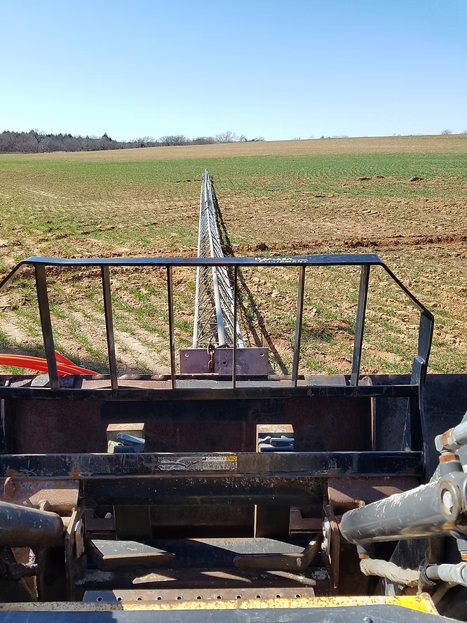
Test antenna support mast and poles
Some of the K0UO QTH is located in a wetland area on a creek bottom, characterized by high alkalinity and salt content. The nearby farmland, extending up to two miles away, has very high conductivity due to its red, iron-rich soil. The primary grounding is provided by a 5400-foot-deep oil well casing. Electrical Conductivity (EC) refers to a material's ability to conduct an electrical current, typically measured in milliSiemens per meter (mS/m). The presence of more ions, whether from acidity or basicity, enhances electrical conductivity, thus increasing the EC in soil. The Wenner "4-point or 4-pin Method" is the most common technique for assessing soil resistivity for broadcasters and communication sites. This method involves spacing probes 5 feet apart to measure resistivity at a 5-foot depth. Similarly, spacing the probes 40 feet apart yields a weighted average soil resistance from the surface down to 40 feet. This raw data is often processed with software to analyze soil resistivity as a function of depth. The accompanying photo shows three wooden pine poles supporting the radiating antenna cables surrounded by water; when the soil is drier, it has a very high salt content and is composed of red, iron-rich dirt. During winter months, up to six Beverage receive antennas, each ranging from 1000 to 1500 feet, are utilized in this area and the adjacent winter wheat fields.


I now use a Re-entrant system of the rhombic arrays which is 90% efficient by re-phasing the power back in the antenna, instead of heating up termination resistors. The K0UO antenna farm is now the largest in the world using wire arrays.


L. B. Cebik, W4RNL modeling
This is for 80 meters, it would need to be a half wave high to control ground loss


Does NEC5 model buried conductors
WA7ARK recommends NEC5 (newer MOM algorithm) from Lawerence Livermore Labs greatly adds to modeling capability (adds buried conductors) and makes it much easier to write models (many less restrictions compared to NEC2d)
Models vs. Prototypes: Why Field Adjustment Will Always be Necessary
L. B. Cebik, W4RNL
TO SEE the complete Blog list check @ https://www.k0uo.com/k0uo
TIP: It is a Blog, so just SKIP the Blogs HEADER and go down to the blog.
RSI Corporation has performed tens of thousands of RF surveys over the past 30 years

The team at RSI Corp. - Radiofrequency Safety International has a proven history of successfully providing certified EH&S EME/RFR compliant surveys, safety training, and solutions to thousands of industry and RF Telecom professionals. RSI courses fulfill the certification requirements for AT&T, Verizon, Rockwell, Collins Aerospace, AIRINC, Bechtel, DoD, Motorola, Black & Veatch, various utility companies, government entities, broadcasters, and most major cell carriers and their contracting organizations. Our authorized OSHA outreach trainers have decades of practical experience, allowing them to deliver safety solutions that ensure compliance with OSHA, FCC, EPA, and FAA regulations while prioritizing employee safety.

The K0UO antenna test range site serves as an invaluable learning environment specifically designed for a variety of Scientific, Technical, Engineering, & Mathematics (STEM). HamSCI antennas projects, in an outdoor real world location. Known as "The K0UO & RSI Corp Antenna University". This unique facility provides students, researchers, and professionals with the opportunity to engage in hands-on experiences that are crucial for understanding the complexities of antenna design, testing, and implementation.
Purpose and Importance of the K0UO EME/RF Antenna Test Range: The primary purpose of the test range is to facilitate practical learning experiences that complement theoretical knowledge. By offering a real-world setting, the site allows participants to observe and interact with antenna systems in various conditions, which is essential for grasping the principles of EMC/EME, RFI & radio frequency (RF) communications and signal propagation.
The site can be used for RDT&E antenna characterization.
electro-optical infrared EO/ISR sensor, operator mission station with FM tactical radios, and data link system.

Features of the Test Range: The test range is equipped with state-of-the-art technology and resources that enable a wide array of experimental setups. Participants can utilize various types of antennas, including directional, omnidirectional, and specialized antennas, to conduct experiments that test their performance under different scenarios. The outdoor location is particularly advantageous as it mimics the actual environments where antennas will be deployed, allowing for more accurate data collection and analysis. Educational Programs and Workshops in addition to individual projects, the K0UO antenna test range hosts a series of educational programs and workshops aimed at fostering interest in STEM fields. These programs are tailored for students of all ages, from elementary school to university level, and are designed to inspire the next generation of engineers and scientists. Through collaborative projects, participants can work in teams, enhancing their problem-solving skills and encouraging innovative thinking.

Intelligence, Surveillance, and Reconnaissance (ISR) form the backbone of effective military strategy. The adoption of AI within ISR systems has dramatically increased the ability to process massive volumes of sensor data, identify threats, and track enemy movements in real-time. Traditional ISR testing and operations relied heavily on human interpretation of imagery and signal intelligence, often limiting the speed and scope of analysis.
A fundamental operational concept known as Agile Combat Employment (ACE) and signature replication is pivotal in modern warfare.
In contemporary military operations, forces employ high-power "Trickster" systems. These systems create a deceptive radio frequency (RF) footprint to mislead enemy signals intelligence (SIGINT) and electronic warfare networks. Large wire arrays are particularly suitable for evaluating these capabilities through various methods.

The Goal: A genuine ISR decoy must do more than emit random noise; it needs to accurately replicate the specific RF signatures of a high-value military target, such as a tactical air command center, an active naval communication hub, or an advanced radar installation.
The Wire Advantage: Large wire arrays, such as distributed feed curtains, V-beams, or re-entrant rhombics, offer significant directivity, high power-handling capacity, and broad bandwidths. Testers introduce specialized waveforms into the wire array to simulate the precise lobe structures, signal timings, and polarization profiles of actual military infrastructure.
2. Over-the-Horizon Deception Modeling
The Goal: Modern peer-adversary SIGINT networks monitor troop and asset locations from vast distances by capturing signals that reflect off the earth's ionosphere, a phenomenon known as skywave propagation.
The Wire Advantage: Unlike short metal antennas that radiate in all directions, a 1,200-foot V-beam or a large curtain array focuses a powerful, directed beam towards a specific global coordinate. By transmitting deceptive waveforms over the horizon via skywave, defense contractors can assess whether a distant simulated adversary would mistake the "fake" signal for a genuine deployment.
3. Drone-Based Far-Field Mapping
To ensure a decoy functions effectively without revealing its deceptive nature through "dead zones" or unintended side lobes, testers map the antenna's signal behavior in three-dimensional space.
Calibrated Instrumentation Drones: Facilities deploy heavy-lift drones equipped with non-ionizing radiation survey instruments and calibrated field strength meters to traverse the far-field pattern of the transmitting array.
Frequency Hopping: Implementing frequency hopping is essential, making low SWR antennas like Rhombic or LPDA ideal for field range testing projects.

This includes exploring new materials, designs, and applications for antennas in various fields such as telecommunications, aerospace, and environmental monitoring. The collaborative nature of the test range encourages the sharing of knowledge and resources, leading to advancements in technology and methodology.
Also an overview of the "Amplified Re-entrant Rhombic K0UO System" as used on a DoD project, which provided reliable and efficient HF communications for a circuit to Guam from the K0UO site in Kansas. see at https://www.k0uo.com/post/understanding-re-entrant-rhombic-array-antennas-design-features-and-applications
Community Engagement: Furthermore, the K0UO antenna test range actively engages with the local community, offering outreach programs that promote STEM education. By partnering with schools and community organizations, the site provides resources and support to inspire young minds to explore careers in science and technology. This engagement not only enriches the educational landscape but also helps to bridge the gap between academia and the community. In summary, the K0UO antenna test range is more than just a testing facility; it is a comprehensive educational platform that plays a vital role in advancing knowledge and skills in the fields of science, technology, engineering, and mathematics. Through its hands-on approach, state-of-the-art resources, and community involvement, it significantly contributes to the development of future innovators and leaders in the STEM disciplines.
Scientific Research at the RSI Corp & K0UO Test Range Site
The test range is strategically located in a quiet RF environment, allowing for the collection of raw data on ionosphere, EMI interactions and the sun, and other geophysical aspects. This data, including noise and signal level measurements, enhances our understanding of the Sun's effects on our space environment and planet. These interactions impact our natural environment, power grid, telecommunications, and satellite navigation systems.
Current and future contributions are expanding a growing repository of raw data, potentially offering new insights into these effects and interactions.

Gold Standard RF Surveyor Certification Class
The RSI Superior Survey Techniques™ training course, by Steven Walz is a University based program developed over a quarter of a century ago by RSI. RSI is the original RF safety expert and wrote the book on RF surveys which is now an industry standard and best practice. This course is the advanced application of scientific sampling techniques necessary for professional health and safety hygiene reports. Participants must be highly qualified and it is strongly recommended attendees have ongoing compliance programs and hold certification such as RSI’s Train the Trainer or Advanced Train the Trainer or an equivalent.
This tried and true scientifically based class, consists of two days of intensive training focused on industry standards for safe and technically sound RF survey data collection.
RSI’s original proven training is the only hands on course available and is designed to build a solid foundation for RF data survey collection. Upon completion of this course, participants will be trained in procedures that are uniform throughout the industry, used nationally and have withstood scrutiny from a variety of governmental entities including the FCC. They will be certified RF safety surveyors.
Photo of FCC Chairman Brendan Carr and Miranda Walz -Allen CEO of RSI Corp, at the FCC Headquarters in DC, Miranda has served on FCC Safety Committees

OTHER OFF SITE PROJECTS
Above is on site photo, of a plant using a very large 10 MW RF Induction Heater used for heating 42" steel pipe for fusion bond epoxy coating. The design, install and RFR safety survey was preformed by Steven Walz of RSI Corp

THE BIG PROJECT STARTING SPRING 2026
K0UO's Major Initiative for 2026 is collaborating with a Department of Defense group, utilizing the Flex ML-9600X/FPA-5K and FPA-10K (not affiliated with Flex Corp) for diversity in transmission and reception, utilizing an AI platform.
A current project at the Range, is testing an AI‑assisted real time propagation and antenna optimization tools from a private ionosonde radar system for the DOD.
Also some antennas on site are currently assisting a group with a project using TDoA (Time Difference of Arrival) Direction Finding (DF) checking integrated statistical localization algorithm which allows the localization of HF transmitters based on AoA (Angle of Arrival).
If you want to stay ahead of the curve, keep an eye on the work coming out of places like the K0UO rhombic farm and antenna test range. We are not just testing antennas; we are shaping the future of radio communication.
Ongoing Scientific Research Projects
K0UO is uniquely positioned in an RF-quiet environment, allowing for the collection of raw data related to the interaction between the Sun and the ionosphere, as well as other aspects of our geophysical environment. This raw data, which encompasses noise data from these interactions and measurements of signal levels, contributes to a substantial dataset. This dataset is instrumental in enhancing our understanding of the enigmatic effects that the Sun and our space environment exert on our planet, both now and in the future.
Allsopp Helikites are in use at the site on projects when needed.
OVERVIEW: RSI Corp. - Radiofrequency Safety International was originally a University based organization located at Northwestern Oklahoma State University, operating under a public-private partnership (RSI Educational Foundation, in 1997 Steve wrote the book, "Superior Survey Techniques". Mobile Radio Technology (MRT) magazine featured RSI Corp and Steve Walz in an RF Survey article, which outlined the requirements on how to conduct non-ionizing radiation Radiofrequency Safety Maximum Permissible Exposure (MPE) analysis, using scientific best management practices. This document set the standard for legally documenting and substantiating compliance. The procedures has since become the standard for documenting radio frequency radiation both nationally and worldwide.
Published in various trade journals and author of a number of white papers, over the years I have been honored to serve on numerous committees, boards and advisory groups ranging from technical, safety, environmental and economic development. Retired from Electrophysics Science work, which specialized in RF/EMI/EMC fields. I have also taught many types of Telecom Safety, Antenna Theory and Technical classes since the late 1990's, (over 35,000 students) live or online through RSI Corp. Other career activities and businesses ranged from Farming, Broadcasting, Oil & Gas services, Concrete Walz Brand of concrete fencing and Wind/Oil & Gas radio tower services.
The classes are part of the Motorola Co-op reimbursement (50%) program; Category 4 Education credits and the Train-the-Trainer option meets RFSO.

RSI Corp is a Environment, Health and Safety Firm, a comprehensive discipline and framework of regulations and best practices for protecting people and the planet by minimizing workplace hazards, preventing injuries and illnesses, ensuring environmental compliance, and managing risks like pollution and waste. It involves creating a safe workplace, adhering to laws from agencies like OSHA and EPA, training employees, and fostering a strong safety culture, for Hyperscale AI data centers and MOC. Since the 1990s, RSI Corp, located in Barber County, Kiowa, KS, has provided expert Environmental Health and Safety (EH&S) services to some of the largest AI data centers and NOCs. Their clients include Verizon, AT&T, T-Mobile, the Department of Defense, Google, UPS, and FedEx.
RSI Corp. 30 years of EHS projects Nationwide
Please accept the attached brief detailing RSI Corporation’s Environmental Health & Safety (EH&S) technical capabilities, specialized electromagnetic field (EMF/RF) safety protocols, and extensive experience supporting Network Operations Centers (NOCs) and hyperscale data centers nationwide.
As Google establishes Project Helium in Barber County, Kansas, RSI Corporation offers a unique combination: national-level expertise in mission-critical EH&S compliance coupled with deep, local operational presence in Barber County.
Our commitment to this location extends far back into its infrastructure development history. Between 2000 and 2017, RSI Corporation CEO Miranda Walz Allen and Steven Walz served on the Barber County Economic Development Board. During that period, our leadership focused on developing the regional power and utility capacity necessary for major technological investments, culminating in two key anchor projects:
The Flat Ridge Wind Farm: Delivering clean, scalable utility-scale renewable generation.
The High-Voltage "Y" Transmission Line Infrastructure: Providing high-reliability bulk power transmission capacity.
These exact energy and grid assets created the resilient power foundation that ultimately made Barber County the ideal home for Project Helium.
Having contributed directly to the economic and energy infrastructure that brought Google to Barber County, RSI Corporation is eager to support Google's buildout and ongoing operations. Our EH&S team provides full turnkey support, including:
Electromagnetic Field (EMF) and Radio Frequency (RF) human exposure evaluations.
OSHA compliance and workplace safety program development for high-density AI compute nodes and NOC facilities.
On-site environmental compliance, health hazard assessments, and ongoing safety training.
We welcome the opportunity to discuss how RSI Corporation can serve as your primary local EH&S partner for any project like Project Helium. Thank you for your investment in our community.
Sincerely,
Miranda Walz Allen
Chief Executive Officer, RSI Corporation
Steven Walz
Director RSI Corporation
General Press Release
We are pleased to submit the attached brief highlighting RSI Corporation’s specialized Environmental Health & Safety (EH&S) capabilities, with specific focus on high-density technology environments, Network Operations Centers (NOCs), and hyperscale AI data centers across the United States.
As Google advances its development of Project Helium in Barber County, RSI Corporation is committed to serving as a trusted, locally rooted partner capable of delivering world-class safety compliance, RF/EMF hazard evaluations, and environmental oversight right here at home.
While RSI Corporation has built a strong national reputation working with critical infrastructure and high-tech facilities across the country, our roots and long-standing commitment remain firmly in Barber County. From 2000 through 2015, both of us had the privilege of serving on the Barber County Economic Development Board. During those seventeen years, our board focused on building the foundational infrastructure required to position Barber County for long-term economic prosperity.
Key milestones from that era include bringing two transformational energy projects to our county:
The Flat Ridge Wind Farm: Establishing substantial, scalable renewable energy generation.
The High-Voltage "Y" Power Transmission Line: Securing the high-capacity power transmission grid necessary for major industrial and tech operations.
It is gratifying to see that the very infrastructure developed during those years laid the groundwork that ultimately attracted Google to select Barber County for Project Helium. Having helped build the grid foundation that made this site possible, RSI Corporation is uniquely positioned to help protect the workforce, community, and environment as Project Helium becomes operational.
We request the opportunity to present our EH&S qualifications to the any group or local development authorities to evaluate local service providers and operational frameworks for this landmark project.
Thank you for your ongoing leadership and dedication to the future of Barber County.
Sincerely,
Miranda Walz Allen
Chief Executive Officer, RSI Corporation
Steven Walz
Director RSI Corporation
The site has UAS Infrastructure with ground-based ADS-B RX systems, Automatic Dependent Surveillance-Broadcast (ADS-B), network of ADS-B receivers to promote safe operations in the airspace.

NOW 2026
100% remote workers and online training and safety programs 24 hours a day 30 years of serving the world, from Kiowa KS in Barber County
The RSI Corp outdoor testing range site at the 4KS Walz Airport
RSI Wind
Walz Broadcasting, Border Line Electric, LMR Two-way radio services, and RSI "Defense Technical Information" Group which focuses on defense telecommunication command and control used by Federal Agencies and military see, https://www.rsicorp.com/dtic
This class is part of the Motorola Co-op reimbursement (50%); Category 4 Education credits. Train-the-Trainer option meets RFSO.
Certification curriculum, Telecom workers/supervisors needing recurrent training; companies wanting customizable plans. Widely used for carrier compliance (e.g., AT&T, Verizon).
"I have been very fortunate and honored to continue military and aviation experiences throughout the years, by occasionally working with Defense Contractors and Government Agencies".
KDOT aviation education. Starting November, 2025 your local school districts can apply for high school aviation education courses that are outlined in the flyer. We have a video posted on our YouTube channel discussing these courses, that you can access here.
If your school is interested in adopting an aviation education program, please feel free to either have them reach out to us or schedule a meeting and include us. With our academic partners, we can answer any questions and walk your school district through the process. We can also put them in touch with other school districts that currently have an aviation education program.
These courses can be adopted anywhere, regardless of how rural or resource constrained your school district may be. There are strategies that can overcome many obstacles. Please help us spread the word.
Ray Seif | Director of Aviation
O: 785-296-6336
M: 785-496-8630
Kansas Department of Transportation
Eisenhower State Office Building
700 SW Harrison St, 9th Floor
Topeka, KS 66603-3745

The K0UO antenna test range site makes use of the 4KS Walz Public airport, known as "Antenna University", and its surrounding area as a practical learning environment for STEM (Scientific, Technical, Engineering, & Mathematics) antenna projects in a real-world outdoor setting. The site has a large outdoor area with a variety of terrain types for conducting user defined experiments. If your group has a University aerospace or antenna research STEM program, please let me know. We support the Amateur Radio Digital Communications and their STEM programs.
 |
K0UO is part of HamSCI, the Ham Radio Science Citizen Investigation, which serves as a platform to promote projects aligned with these goals:
Enhance scientific research and understanding through amateur radio activities.
Encourage the creation of new technologies to support this research.
Offer educational opportunities for both the amateur community and the general public.
HamSCI facilitates collaboration between professional researchers and amateur radio operators. It helps establish and maintain standards and agreements among all participants.
What is HamSCI's scientific focus?
HamSCI was initiated by ham-scientists who explore upper atmospheric and space physics. They realized that projects like the Reverse Beacon Network, WSPRNet, PSKReporter, DX Cluster, ClubLog, and others are producing extensive data sets that could offer valuable insights into the Earth's ionosphere and related systems. Consequently, HamSCI initially concentrates on these research areas. In the future, additional researchers may join and expand its scope. For scientists, collaborating with the amateur radio community provides access to individually managed stations, available in the hundreds across numerous countries, with receive and transmit capabilities across the electromagnetic spectrum, easily identifiable in areas of interest and deployable to remote locations.
Science Questions
How does the ionosphere react to inputs from space and the neutral atmosphere?
How does the ionosphere interact with the neutral atmosphere and space?
What causes medium and large scale traveling ionospheric disturbances?
What are the origins of Sporadic E?
Amateur Radio Questions
How do phenomena like solar flares, geomagnetic storms, and traveling ionospheric disturbances impact radio wave propagation?
How does ionospheric science assist amateur radio operators in enhancing communications?
How can I leverage my existing radio equipment for scientific initiatives?
The KØUO Rhombic Antenna Farm and Antenna Test Range: Home to the World's Largest amateur radio (ham), High Frequency (HF) Wire Arrays still on the air, miles of wire in the air and on the air daily. We are using AI which is now becoming an advanced tool in analyzing, developing, and expanding research in RF and antennas. K0UO is also now using AI, making it one of the largest and most sophisticated amateur radio stations in the world
73
K0UO/V31KW
Seve Walz

The test range location @
Antenna University
The site emphasizes the scientific method: model → build → far-field test → refine
T: 888-830-5648
F: 620-825-4324

SEE ALL BLOGS Here, & Just Skip the first few pages, and go to the Blog List


It's really interesting to see what ham radio operators can do and also with incorporate that their businesses.
They have been surveying our MOCs and wireless sites and also training our worker for years
RSI is a Great Team
Thank you Steve for hosting our WSU drone engineering team at your airport and antenna test site. We flew the 1200 plus acres, it's truly amazing to be at the world's largest antennatest range out in the country away from all types of interference
Steve has a very complex setup, and can really test and understand how the antennas work in the real world
Crazy interesting that someone could build all this for amateur radio use