


The Ground Around Your Antenna
- skylarkcolo

- Oct 29, 2023
- 12 min read
Updated: Jun 11

K0UO near Kiowa, KS has many types of High-Performance Antennas: Using large High Frequency HF stacked LPDA-Yagi beams, Rhombics, V Beams, Curtain arrays, Four-square phased verticals on specific bands, optimized for low noise and very efficient and high gain.
The site emphasizes the scientific method: model → build → far-field test → refine
Modeling an antenna over real terrain gives you a visual picture of how terrain impacts performance. You can use a model to:
Determine optimum height for antennas on an existing tower
Compare different tower locations for performance
Compare different sites for performance
K0UO uses a software package called HFTA or HF Terrain Analysis.
HFTA is a great graphical tool but only models the antenna over at most four azimuth values at a time. A good program is intended to evaluate different antenna heights over terrain in all directions.
HFTA models horizontal antennas at specified heights over terrain and plots the modeled antenna gain at different elevation angles.
The Fresnel region is the area where the radiation field pattern or shape is still being formed. It may or may not include induction field areas. Physically large arrays like K0UO's have a physically large Fresnel zone extending out a few wavelengths. The field impedance may or may not have already been established in the Fresnel zone.
The K0UO QTH is surrounded by a natural low-lands called wetlands on a creek bottom, which is highly alkaline and has a high salt content. The normal conductivity of the nearby farmland up to two miles away is very high, it is red soil, which is high in iron. What is Electrical Conductivity (EC)? It is the ability of a material to transmit (conduct) an electrical current and is commonly expressed in units of milliSiemens per meter (mS/m). The more acidic or basic something is, the more ions there are. The higher ions the better the electrical conductivity is. Therefore, the more acidic or basic in the soil, the higher the EC will be. To test, the Wenner "4-point or 4 pin Method" is used, which is by far the most used test method to measure the resistivity of soil for broadcasters and comm-sites. The basic premise of the soil resistivity test is that probes spaced at 5’ distance across the earth, will read 5’ in depth. The same is true if you space the probes 40’ across the earth, you get a weighted average soil resistance from 0’ down to 40’ in depth, and all points in between. This raw data is usually processed with computer software to determine the actual resistivity of the soil as a function of depth.

It is only after you actually measure the RF radiation pattern of what you simulate that you will gain a comprehensive understanding of what the antenna is truly doing at your specific location. This process involves several critical steps that are essential for accurate assessment and analysis.
Modern programs based on NEC2/NEC4 aim to model the absorption of RF in the ground's electrical conductivity around an antenna using the Sommerfeld-Norton ground model. Older modeling methods are limited by an inadequate approach to simulating loss and ground reflections at low angles. The interaction between the antenna and the ground necessary to form a skywave occurs within a radial distance of 1 to 5 wavelengths from the antenna. Some antennas are more affected by ground losses than others. Nearby objects such as buildings, trees, towers, antennas, and fences significantly influence the antenna's performance, which models may not accurately represent. Real-world patterns might differ from theoretical models unless the ground's electrical conductivity is tested. Only after measuring the RF radiation pattern of your simulation will you truly understand the antenna's behavior at your location.

Acceptance testing in the Far Field was complete (12/2019) for the Curtain Array. Metrology is the scientific study of measurement just the ability to measure alone is insufficient; standardization is crucial for measurements to be meaningful. The test verified on 40 & 20 meters the design maximum gain, the azimuth of the maximum gain, steering of both direction and azimuth, design side-lobes, and the back-to-front ratio. A calibrated, W&G EMR meter for both the E and H field is used, with the use of a portable tower in the far field at precise predetermined positions. This allowed the for the most suitable method of conducting the test measurements. The analysis and its feedback mechanisms are a major part of K0UO's projects.
All tests at K0UO are conducted in the Far Fields or the Fraunhofer zone, which is the area where changes in the distance from the antenna no longer result in a noticeable change in pattern shape or field impedance.
Modern programs based on NEC2/NEC4 attempt to model loss (absorption of RF) in the ground's electrical conductivity beneath and around an antenna (using the Sommerfeld-Norton ground model). Older modelers are limited to using an inadequate method for modeling loss and ground reflections at low angles. To form a skywave, all relevant interactions between the antenna and the ground beneath it occur within a distance of 1 to 5 wavelengths radially out from the antenna. Some antennas are more sensitive to ground losses than others. Surrounding objects in the antenna's near field, such as buildings, trees, towers, antennas, and fences, also play a significant role that models do not show. Real-world patterns may not match theoretical models unless you have tested the ground's electrical conductivity. Only after you actually measure, the RF radiation pattern of what you simulate will you understand what the antenna is truly doing at your location.
Note, this K0UO blog uses dB gain, not dBi when providing antenna gain data, don't be fooled by dBi.

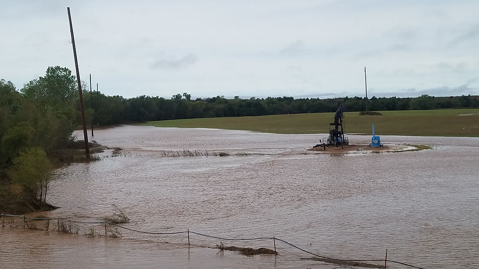
The photo at the K0UO site below shows 3 of the 100 foot wood poles holding the radiating antenna cables surrounded by water, when dryer the soil has a very high salt consistency and is red dirt (high in iron). Up to 6 Beverage receive antennas are used in the winter months each 1000 to 1500ft are used in this area and the winter wheat fields near by.

The terrain surrounding a radio station plays a crucial role in determining the strength and quality of the signal that is radiated from its antennas. When considering the placement of antennas, the geographical features of the area must be taken into account, as they can significantly influence the propagation of radio waves. For instance, a station situated in a valley will inherently face challenges in transmitting signals effectively. The surrounding hills and mountains can obstruct and absorb the radio waves, leading to a diminished range and weaker signal strength. In contrast, a station positioned on a ridge line or elevated area above the surrounding terrain is likely to experience a much more favorable broadcasting environment. The elevation allows for a clearer line of sight to potential receivers, thereby enhancing the distance and clarity of the transmitted signals.
However, the impact of terrain on signal strength extends beyond these straightforward scenarios. Many individuals may not fully grasp how various topographical features can create complex interactions that affect their station's performance. For example, trees, buildings, and other structures can create reflections and diffractions of the radio waves, leading to areas of signal enhancement or, conversely, dead zones where the signal is weak or non-existent. Additionally, the type of soil and vegetation in the area can also play a role in how signals propagate. Wet, dense vegetation may absorb more signal energy than dry, sparse terrain, further complicating the transmission landscape.
To effectively mitigate these effects, station operators must consider various strategies related to the choice and placement of antennas. This may involve selecting antennas that are specifically designed to operate effectively in challenging environments or adjusting the height and orientation of existing antennas to optimize their performance. Utilizing directional antennas can also be beneficial, as they can focus the signal in a specific direction, thereby minimizing the effects of obstacles in other areas. Furthermore, conducting a thorough site survey to assess the surrounding terrain can provide valuable insights into how to best position antennas for maximum efficacy.
In conclusion, understanding the intricate relationship between terrain and signal strength is essential for anyone operating a radio station. By recognizing the potential challenges posed by geographical features and employing strategic measures to address these issues, station operators can significantly enhance their broadcasting capabilities, ensuring a more reliable and robust signal for their audience.
A Ground Is Just a Ground--Unless It Is a Model of a Ground!
Using the Drone for ground info

Agriculture soil mapping equipment is really advancing soil analysis mapping, revolutionizing the way farmers and agronomists understand and manage their land. With the integration of sophisticated technologies and innovative tools, the process of soil analysis has become more precise and efficient, allowing for better decision-making in crop management and soil health maintenance. And can be used at RF telecommunications sites to understand the ground.

The soil temperature and compaction can significantly affect the electrical conductivity (EC) measurements, which are crucial for understanding soil properties. As soil temperature approaches the freezing point of water, it has been observed that soil EC measurements tend to decrease. This phenomenon occurs because, below freezing temperatures, the soil pores become increasingly insulated from one another, leading to a rapid decline in overall soil EC. The reduction in temperature affects the mobility of ions within the soil, which are essential for conducting electricity. Consequently, the presence of ions, such as those found in saline soils, along with the moisture content in the soil pores, plays a vital role in enhancing soil EC levels. Higher salinity levels generally lead to increased conductivity, providing valuable insights into soil health and fertility.
Recent advancements in technology have led to the development of new types of EC sensors that possess enhanced capabilities. These modern sensors can now accurately identify distinct areas within the soil that consist of different materials, such as sand, rock, or clay. This information is critical for farmers as it helps them understand the composition of their soil, which directly influences crop growth and yield. Additionally, these sensors provide valuable data regarding topsoil depth, which is essential for effective planting and irrigation strategies. Understanding the variation in topsoil depth can help in optimizing seed placement and nutrient management, ultimately leading to improved crop performance.
Moreover, factors such as water content and soil porosity have a significant impact on the conduction of electrical radio frequency (RF) current through the soil. The moisture content within the soil affects how well it can conduct electricity; wetter soils typically exhibit higher conductivity due to the increased mobility of ions in the presence of water. Similarly, soil porosity, which refers to the amount of space between soil particles, influences the movement of water and air within the soil, thereby affecting its overall electrical properties.
Understanding these relationships is essential for effective RF site grounding management practices, enabling farmers to make informed decisions about irrigation, fertilization, and crop selection based on the specific conditions of their fields.
Using the Drone in the Near and Far-field

47 CFR 73.190 of the Commission’s Rules contains a map of the estimated effective ground conductivity in the United States. This data is used to predict the propagation of AM signals across the United States. A higher ground conductivity indicates better AM propagation characteristics. The map shows that the ground conductivity in the U.S. ranges between 0.5 and 30 millimhos (or millisiemens) per meter. The conductivity of seawater is 5,000 millimhos per meter, resulting in the best propagation of AM signals.
Dust Bowl Days
The large wire antennas, which were a common sight during the early 20th century, would accumulate static electricity due to their extensive surface area and exposure to the elements. The combination of dry winds and persistent dust storms characteristic of the region would cause these antennas to crackle with intense static electricity, creating an eerie and almost otherworldly atmosphere. This phenomenon was not merely a nuisance; it was a striking manifestation of the environmental conditions that prevailed during that time.
During the tumultuous 1930s Dust Bowl era in Kansas, the effects of static electricity became alarmingly pronounced. The relentless winds whipped up the arid soil, lifting fine dust particles into the air and creating vast clouds that obscured the sun. As these dust particles swirled and collided, they generated significant static charge. The accumulation of this charge between the ground and the airborne dust was so severe that blue flames would leap from barbed wire fences, illuminating the darkened landscape with an eerie glow. These sparks were not just a visual spectacle; they posed real dangers to those who lived in the area. In fact, people who shook hands during these dry conditions could generate a spark so powerful that it could knock them off their feet, leaving them startled and disoriented.
To combat the hazards posed by static electricity, particularly in relation to automobiles, motorists found themselves adapting to the challenging conditions of dust storms. One common practice involved dragging chains from the back of their cars to ground them effectively. This simple yet ingenious method served to dissipate the built-up static charge, thus preventing any potential short circuits that could disrupt engines or car radios. The sight of cars trailing chains through the swirling dust became emblematic of the era, a testament to human ingenuity in the face of nature's relentless challenges.
As dust particles reached a certain density, the charge level increased significantly, leading to even more dramatic displays of static electricity. This increase in charge was not just a random occurrence; it was a direct result of the physical interactions between the particles as they jostled against one another in the turbulent air. The more densely packed the dust became, the greater the likelihood of static buildup, culminating in spectacular discharges that could ignite nearby materials or create sparks that startled both people and animals alike. The interplay between the environment and these static charges painted a vivid picture of the struggles faced by those living in the heart of the Dust Bowl, where every gust of wind could bring both beauty and peril in equal measure.
Imagine dust particles as small spheres, each with two hemispheres. When polarized, one hemisphere becomes positive and the other negative. Positive charges attract negative charges, so a negatively charged hemisphere on one dust particle can attract a positively charged hemisphere on another. When they meet, they neutralize by transferring an electron from the negatively charged hemisphere to the positively charged one.
As dust storms moved through, they could short out electrical systems, telephones, and cars with RFI. The storms could also disrupt radio stations.
The K0UO antenna test range site utilizes the 4KS Walz airport, and its surrounding area as a practical learning environment for Scientific, Technical, Engineering, & Mathematics (STEM) antenna projects in an outdoor real-world setting. If your group has an University aerospace or antenna research STEM program, let me know.
A word about modeling: You no longer need the latest modeling software, as it's design is rapidly evolving with Artificial Intelligence.
We started integrating AI with modeling in 2024, and now have developed an AI analysis platform focused on antenna performance and specific parameters. Be cautious and invest time in setting the correct parameters for your "AI platform".
One high end paid AI platform is now using AN-SOF, which is a robust simulation engine designed for the modeling and analysis of complex antenna systems and radiating structures.
Gain total spatial awareness of your antenna’s performance with immersive 3D rendering. AN-3D Pattern utilizes colored mesh and surface mapping to visualize radiation lobes with professional clarity.
Creating a well-designed platform using scientific and engineering knowledge is crucial.
Relying solely on ChatGPT is not the solution at all!
The K0UO & RSI Corp platform, which uses Artificial Intelligence to design antennas, and to do HF Terrain Analysis is much more reliable, and completes the process in about 5% of the time required by traditional modeling programs. Setting it up requires time, similar to the initial setup of the original computer modeling software. It's easy to make mistakes by assuming artificial intelligence can operate without errors.
After designing something, we now have the advantage of using our outdoor testing range to validate the results. I consider it essential to confirm results and assess performance in real-world conditions. My team has collaborated with several commercial clients to do just that.
I started with calculators, and some of us are old enough to remember using slide rules and pencils, before moving to computer modeling. It's astonishing to see how far we've come, and in a few more years, like it or not AI will further revolutionize oftware package called Terrain Analysis and antenna design.
The KØUO Rhombic Antenna Farm and Antenna Test Range: Home to the World's Largest amateur radio (ham), High Frequency (HF) Wire Arrays, miles of wire in the air and on the air daily.
See Steve's RF Testing Team, with over 30,000 RF Telcom sites tested, overiew at, https://en.wikipedia.org/wiki/RSI_Corporation
And RSI Corp web site at, https://www.rsicorp.com/
Electrical quality of the soil beneath a horizontal antenna
See all at blogs
By L. B. Cebik, W4RNL/SK


Hams need to know about their ground.
Steve has done Extensive ground conductivity testing, using advanced soil analysis and drone-based sensors to optimize RF propagation