


Rhombic Best Modeling INFO
- skylarkcolo

- May 23, 2021
- 7 min read
I model all my antennas using NEC5 and HFTA (High Frequency Terrain Analysis) to evaluate the take of angle of the various antennas over real ground.
My antennas look like this

This site emphasizes the scientific method: model → build → far-field test → refine

An interesting feature of traveling-wave wire antennas which are terminated with a load resistor. On account of this, the forward transmit power gain is lower than what might have been otherwise. Therefore, a practical antenna of this type will have higher gain in receive mode due to Receive Directivity Factor (RDF) than the forward power gain in transmit mode
This has led to a myth, especially amongst a large section of amateur radio operators that these antennas are receive-only antennas and not suitable as transmitting antennas. Nothing can be farther from the truth. One must realize, that some of the other popular antennas which are commonly used by amateur radio operators too have a differential between the RDF gain and power gain. Though it is true that the differential is more pronounced in the case of these antennas.
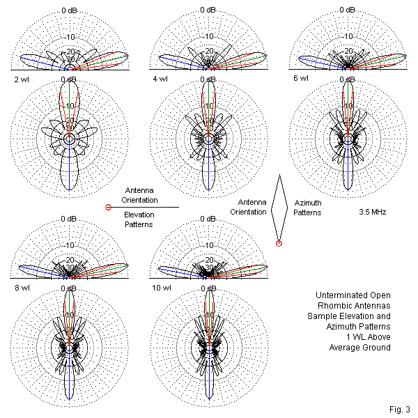
Unlike multi-band resonant wire antennas, the traveling wave antennas have a uniformly directed radiation pattern which does not change drastically with the frequency band of operation. In other words, the direction of the radiating lobes of traveling-wave antennas remains more-or-less same irrespective of the operating band, whereas, in the case of multi-band resonant wire antennas, the direction of azimuth orientation of the main lobe may differ from band to band. Although the upper elevation angles still bristle with lobes, they are generally all of low strength and therefore untroublesome to antenna performance.
Basic rhombic calculations emerge from a situation that is usually not very realistic for the average amateur installation. The premise is that angle A represents 2 different angles in the antenna installation. First, it represents the elevation angle of maximum radiation. Hence,
HWL = [1 / (4 sin A)]
where HWL is the required antenna height in wavelengths. As well, angle A represents the required V'ing angle, the same angle that we used in the V-antennas. To align the major lobe with the elevation angle, we calculate the leg-length as follows:
LWL = [0.371 / (sin2 A)]
where LWL is the leg-length in wavelengths. For maximum gain at the chosen elevation angle,
LWL = [0.5 / (sin2 A)]
For the best modeling data please see
Models vs. Prototypes: Why Field Adjustment Will Always be Necessary
L. B. Cebik, W4RNL/SK
For Design see
TO SEE the complete Blog list check @ https://www.k0uo.com/k0uo
Rhombic or Yagis
VK3MO, Ian also has a stacked rhombic antenna with 8 wavelengths on a leg giving a total of 1340m of radiating wire. The upper rhombic is at 40M and the lower rhombic is at 21M. The rhombic had a gain of 23dBi at a take off angle of 5 degrees on 20M and is directed at New York. The rhombic was modeled using EZNEC and it has 3dB more gain than the 5/5/5/5 yagis Both the yagis and the rhombic have a take off angle of 5 degrees which allows a comparison between the two antennas in the direction of New York. Ian sees see the 3 dB advantage which validates the accuracy of the NEC antenna modelling software.
It is important to recognize that the majority of HF amateur radio Yagi beam and HF wire antennas, as well as many commercial HF beams, have not been evaluated on antenna test ranges today.
Numerous VHF and higher band antennas have been informally tested by groups such as The Central States VHF Society and Microwave Update, which annually establish amateur test ranges at their conferences. This process is advantageous as it exposes shortcomings in certain manufacturers' models and claims.
However, there is a complete absence of real-world far-field testing for HF antennas, such as wire-based and high-performance Yagi beams. This lack of empirical data is particularly concerning given the critical role that these antennas play in effective high-frequency communication. Far-field testing is essential because it allows for the evaluation of an antenna's performance in realistic conditions, including factors such as signal propagation, interference, and environmental influences that can significantly affect performance. Without this vital testing, consumers are left to rely heavily on manufacturer specifications and promotional materials, which often present an overly optimistic view of an antenna's capabilities. Much of the manufacturer's documentation can be quite misleading to consumers, as it may focus on idealized scenarios that do not account for the complexities of real-world operation. For instance, specifications might highlight maximum gain or range under perfect conditions, without addressing the typical challenges encountered in various environments, such as urban areas with high levels of electromagnetic interference or rural settings with varying terrain. Moreover, the absence of standardized testing protocols means that there is no universally accepted method for comparing different antennas. This can lead to confusion among consumers who are trying to make informed purchasing decisions. They may find themselves comparing antennas based on specifications that are not directly comparable or even based on marketing jargon that lacks clear definitions. In addition, the reliance on theoretical models and simulations, rather than practical testing, can result in discrepancies between expected and actual performance. For example, while a Yagi beam might be touted for its directional capabilities, without far-field testing, potential users might not fully understand how its performance can be impacted by factors such as nearby structures, atmospheric conditions, or even the quality of the installation. Furthermore, the lack of independent testing organizations that specialize in HF antennas exacerbates the issue. Consumers would benefit greatly from third-party evaluations that provide unbiased assessments of antenna performance across various conditions. This would not only enhance consumer confidence but also encourage manufacturers to produce more reliable and rigorously tested products. In summary, the current landscape of HF antenna testing reveals significant gaps that can lead to misinformed decisions by consumers. The absence of real-world far-field testing for wire-based and high-performance Yagi beams, coupled with potentially misleading manufacturer documentation, underscores the need for greater transparency and accountability in the industry. Until such measures are implemented, users may continue to face challenges in selecting the most suitable antennas for their specific communication needs.
WA7ARK recommends NEC5 (newer MOM algorithm) from Lawerence Livermore Labs greatly adds to modeling capability (adds buried conductors) and makes it much easier to write models (many less restrictions compared to NEC2d)
NOTE
MININEC type ground among others. Corrections to the command line NEC-5 program address the following bugs:
Incorrect gain was reported when using current sources.
Near field and surface wave results were incorrect when using MININEC type ground.
Inhibiting Sommerfeld ground file writing by specifying NOFILE as the file name caused a crash.
An internal array dimension (NETSOLMAXX in SUBROUTINE ALLOC_NETWORK_SOL) wasn’t large enough and could cause a crash under some conditions.
Errors could occur or the program crash if any NT or TL port was placed at end 1 of a segment.
A word about modeling: You no longer need the latest modeling software, as it's design is rapidly evolving with Artificial Intelligence.
We started integrating AI with modeling in 2024, and now have developed an AI analysis platform focused on antenna performance and specific parameters. Be cautious and invest time in setting the correct parameters for your "AI platform".
Creating a well-designed platform using scientific and engineering knowledge is crucial.
Relying solely on ChatGPT is not the solution at all!
The K0UO & RSI Corp platform, which uses Artificial Intelligence to design traveling wave and other antennas, is much more reliable, and completes the process in about 5% of the time required by traditional modeling programs. Setting it up requires time, similar to the initial setup of the original computer modeling software. It's easy to make mistakes by assuming artificial intelligence can operate without errors.
After designing something, we now have the advantage of using our outdoor testing range to validate the results. I consider it essential to confirm results and assess performance in real-world conditions. My team has collaborated with several commercial clients to do just that.
I started with calculators, and some of us are old enough to remember using slide rules and pencils, before moving to computer modeling. It's astonishing to see how far we've come, and in a few more years, like it or not AI will further revolutionize antenna design.
NOTE, Don't underestimate the performance of the Rhombic, unless you have personally built and used one. Because of their excessive size (area) covering many acres, you see their real advantage of thousands of feet of wire in the air, which creates receive signal diversity, by capturing signals at different times and different angles, vastly eliminating fading QSB, and firing out the transmitted RF in the same way. Traveling wave antennas are very unique and unlike many other antenna in common use and modeling will not show this.
The K0UO antenna test range site makes use of the 4KS Walz airport and its surrounding area as a practical learning environment for STEM (Scientific, Technical, Engineering, & Mathematics) antenna projects in a real-world outdoor setting. If your group has a university aerospace or antenna research STEM program, please let me know.
The KØUO Rhombic Antenna Farm and Antenna Test Range: Home to the World's Largest amateur radio (ham), High Frequency (HF) Wire Arrays, miles of wire in the air and on the air daily.

The "KING of Wire Antennas" is a Rhombic. which the ARRL and many other ham radio organizations world wide use the diamond symbol as their logo also. A rhombic diamond array is must be the logo, not a Blaw-Knox tower which does not resemble a diamond shaped Rhombic array!
K0UO emphasizes the scientific method: model → build → far-field test → refine
"I hope others will carry on the tradition, and art of building the large Rhombic Arrays in the future". It is truly the "PHD" of wire antennas.


Comments