


Rhombic Antenna Array
- skylarkcolo

- Nov 2, 2024
- 25 min read
Updated: 13 hours ago
The ARRL and RSGB Diamond Logos, looks like a Rhombic Antenna, which is the "PHD" of HF wire antennas
The Rhombic is the antenna that won WW2 for the Western Allies


FCC ASR Number
The Rhombic antenna array was designed in 1931 by Ed Bruce and Harald Friis
It was commonly used in the HF shortwave point to point and broadcast as a broadband directional antenna, it is also known as a diamond antenna. See 1931 patent, US 2285565A1 I (aktuellum.com)
There are two primary types of Rhombic antennas that are widely recognized in the field of radio frequency communications: The resonant Rhombic antenna and the terminated Rhombic antenna. Each of these antenna types has unique characteristics and applications that make them suitable for different scenarios in wireless communication. And K0UO uses a third type, which will be discussed later in this post which is highly efficient (90%).
Resonant Rhombic Antenna
The resonant Rhombic antenna is characterized by its bidirectional radiation pattern. This means that it can effectively transmit and receive signals in two opposite directions, making it an excellent choice for applications where communication is required over long distances and in both directions. The design of the resonant Rhombic antenna typically consists of four wire elements arranged in a diamond shape, which allows for efficient signal propagation.

One of the key features of the resonant Rhombic antenna is its ability to operate at a specific frequency range, which is determined by its dimensions. The antenna is designed to resonate at a particular frequency, ensuring that it can efficiently transmit and receive signals within that frequency band. This resonant behavior not only enhances the antenna's performance but also helps to minimize signal loss, making it a preferred option for high-frequency applications, such as shortwave radio communications.
In addition to its bidirectional capabilities, the resonant Rhombic antenna is also known for its very high gain and low noise RX characteristics. This makes it suitable for applications that require clear and reliable communication over considerable distances, such as in amateur radio, broadcasting, or in military communications. At this time K0UO is the only Rhombic station using re-phasing. These are the largest wire antennas in use by an amateur radio stations with true 14 to +18 dBd of gain. Signal to noise is excellent at the Rhombic farm. Keep in mind that K0UO is comparing rhombics to large stacked single band yagis beams that were previously used on 195-foot rotating towers at K0UO, and has tested both yagis and rhombics on the RSI Corp antenna test range. "Rhombics bets Beams"
Note, this K0UO blog uses dB gain, not dBi when providing antenna gain data, don't be fooled by dBi.
So many hams that I talk to now days, ask me what is a Rhombic, and where can I buy one? Most have never heard of the classic array. However if they are U.S. hams, they should have reviewed three questions on the ham test about Rhombic arrays, the questions have been on the ham test for years.

Terminated Rhombic Antenna
On the other hand, the terminated Rhombic antenna is designed to be unidirectional, meaning it is optimized to transmit and receive signals primarily in one direction. This directional capability is achieved by incorporating a resistive termination at the antenna's far end, which helps to absorb unwanted reflections and reduces the amount of signal that is radiated in the opposite direction. As a result, the terminated Rhombic antenna can provide a more focused and stronger signal in its intended direction, making it highly effective for point-to-point communication links.
The design of the terminated Rhombic antenna also follows a similar diamond-shaped configuration, but with the addition of the termination, which plays a crucial role in its performance. The termination not only enhances the antenna's directivity but also improves its impedance matching, allowing for better energy transfer between the antenna and the transmission line. This feature is particularly beneficial in applications where minimizing interference and maximizing signal strength are paramount.
While the terminated Rhombic antenna may not offer the same bidirectional capabilities as its resonant counterpart, it compensates for this by providing a more powerful signal in its designated direction. This makes it an ideal choice for applications such as broadcasting, where a strong signal is required to reach a specific audience or geographic area.
In summary, the two types of Rhombic antennas—the resonant Rhombic antenna and the terminated Rhombic antenna—serve distinct purposes in the realm of radio frequency communications. The resonant Rhombic antenna, with its bidirectional capabilities, is well-suited for applications requiring two-way communication, while the terminated Rhombic antenna excels in scenarios demanding unidirectional signal transmission. Each antenna type offers unique advantages that cater to the diverse needs of communication systems, highlighting the importance of selecting the appropriate antenna based on the specific requirements of the application at hand.
Generally, the antenna is terminated with a value equivalent to characteristic impedance thereby causing the non-resonant condition to be establish. Making the radiation characteristics of the antenna are unidirectional. When the power through the feed lines either the 2-wire transmission line is provided to the antenna. Then the generated current travels through the legs of the Rhombic antenna (Fast Traveling Wave).
These currents flow through the antenna and generate radio waves that progress in one direction through the legs of the antenna.
Now there are three types of Rhombics in use.
The Third type of Rhombic is a K0UO Re-entrant
I don't terminate my antennas, but use what is called, re-entrant line termination for a higher 90% efficiency, see more about that system later in this blog post. The Re-entrant Rhombic array is one of the highest forward gain HF antennas, with its 90% efficiency. Read more about this later in this post and others.

The Proper impedance matching between an antenna and its transmission line is crucial in maximizing signal efficiency and reducing unwanted reflections, which can cause major losses in RF power going to the antenna. Impedance matching keeps the impedance of the antenna and the transmission line the same in order to see the least amount of signal per watt lost. Remember there is no SWR on a traveling wave antenna. It's only the mismatching between the 600 to 800 ohm of the antenna, and the 50 ohm transmission line, that creates it.
Two great books to read, Rhombic Antenna Design, by A.E. Harper of Bell Labs, and W6AM, which shows Dow Wallace’s antenna farm after WW 2 to the 1980s.

Rhombic Antennas were used in WWII Military Communications, by Harnessing the RF Power, to Win the War for the Allies.
Historic Preservation: The K0UO station diligently preserves and uses components and insulators from renowned, historic radio arrays, including those from W6AM (Don Wallace), W7YRV Roy, BBC, Voice of America (VOA), and many others.
"The K0UO station is unlike any other ham station globally," making it truly unique as a Big Gun Mega Station. It is one of the few capable of constructing and utilizing very large Rhombic and V Beams, along with a variety of other antennas. K0UO features the largest operational HF wire antenna in the world.
The key concept with traveling-wave type antennas like a Rhombic or Vee Beam (V-Beam) is that there are no standing waves, on the antenna itself, the current and voltage levels are the same everywhere along the antenna conductors,. But you still have to match it to the fed-line.
The Rhombic is the largest and most refined of the HF long-wire antennas, consisting of two Vs, open-end to open-end. The result is 4 wires contributing aligned lobes for higher gain and narrower beam-width. The Rhombic suppresses unwanted side lobes better than the V antenna. The K0UO site has miles or wire very high gain "Rhombic Curtain and V Beam arrays", They are the King of HF Wire Antennas that no yagi can bet.
See SWR photo below it shows one of my antennas, now this is flat, no tuner!

The Rhombic antenna is a wide-band progressive traveling-wave (fast-wave) antenna, made of two acute-angle V-beams placed end-to-end and terminated in an open circuit or in a resistive load. Each side of the antenna is made of two legs of length "L" and as a whole the antenna has the shape of a rhombus, that is, the opposite angles are of the same value. The non-terminated Rhombic antenna is bi-directional, whereas the terminated Rhombic antenna is directional. The Rhombic antenna is useful over a wide frequency range. Although some changes in gain, directivity, and characteristic impedance do occur with a change in operating frequency, these changes are small enough to be neglected. A rhombic antenna design works best at a height of one-half to a full wavelength at the lowest frequency.
So: K0UO has No waiting for a rotator to turn, the system has every direction, every band, every time.
To be effective, an efficient station must balance performance, ergonomics, and reliability.

Switching speed depends on whether the movement for a beam and is mechanical, however it is electrical and instantaneous with a Rhombic array.
Rhombic Arrays (Instantaneous): Because these are typically fixed wire structures, changing direction is done through relay switching. By having multiple rhombics pointed in different fixed directions (e.g., every 25°), you can switch between them instantly—typically in milliseconds—at the press of a button or via AI automated software now being used at K0UO.
Stacked Yagi Beams (Slower Mechanical): To change the direction of a stacked Yagi beam, you must physically rotate the entire mast and antenna assembly using a mechanical rotor.
Rotation Time: This can take anywhere from 60 to 120+ seconds to complete a full 360° turn, depending on the rotor's speed and the antenna's mass.
Phasing Options: While you can use a relay switching system to select different combinations of antennas within a stack to adjust elevation or gain, you still have to wait for the rotors to reposition and move to a new target direction try doing this for 24 hours for a contest.

The Rhombic is an equilateral parallelogram shaped antenna, it has two opposite acute angles. The tilt angle, θ is approximately equal to 90° minus the angle of major lobe. Rhombic antenna works under the principle of a fast traveling wave antenna. It is setup in the form of a rhombus or diamond shape and is normally suspended horizontally above the surface of the earth, but can be made vertical. It works great for long-distance F-layer propagation due to low vertical radiation angle, however it does have some higher radiation lobes which were thought as wasted power for long point to point use however for ham radio this helps fill in closer in coverage, but overlooked in modeling and a major advantage of the antenna for ham radio use, for making more QSOs.
In designing the Rhombic it has to be kept in mind that length of all the four conductive wires must be equal, ranging between one wavelength, to over four. However, the opposite acute angles of the rhombus must be equal.
To avoid reflections of the traveling wave the opposite end of the antenna feed line is terminated with a properly adjusted resistor. This leads to the absence of standing waves in any of the legs of the antenna. This absorption ensures that the current maintains a progressive phase along the antenna, supporting unidirectional wave travel and stable radiation patterns. By matching the resistor value to the antenna’s characteristic impedance, reflections are minimized, resulting in consistent traveling wave behavior and improved directionality and bandwidth. The value of load resistance is generally around 600 to 800 ohms which is also the impedance. The Voice of America antenna system at the Bethany, OH Relay Station used re-entrant Rhombics, which were 90% efficient, by re-phasing the power, instead of heating up termination resistors. My antennas also uses the re-entrant system, the Rhombic is terminated in a transmission line, which in turn is coupled back to the input through the proper voltage-matching, and phasing networks.
The antenna input impedance and radiation pattern are constant over a 4:1 or more range of frequencies. Their impedance is constant over a frequency range 4:1 or more, with the forward gain increasing at 6 dB per octave.
The resultant pattern is the cumulative effect of the radiation at all four legs of the antenna. This pattern is directional, it can be made bi-directional by removing the terminating resistance.
The maximum gain from a Rhombic is along the direction of the main axis, which passes through the feed point to terminate in free space. The polarization obtained from a horizontal Rhombic is in the plane of rhombus, which is horizontal. But portions of the radiation, which do not combine with the main lobe, result in considerable side lobes having both horizontal and vertical polarization, which can be very advantageous for ham radio use.
The old books say, "The gain of a rhombic with side lengths of four to five wavelengths is over 40 times that of a half wave dipole. About one half of this gain is realized by using two wave lengths to each of the four sides" From the old DoD Book,.https://www.mapability.com/ei8ic/rhombic/text.php#:~:text=The%20gain%20of%20a%20rhombic,1
Maximum Size
In modeling it seems to show that the maximum useable size of a rhombic is about 5 or 6 wavelengths per side. Much larger than this and the main lobe will split into a "V" pattern and you gain little else. A practical gain of around 16-18 dBd seems to be the peak of gain, but more array can be phased.
The gain of a rhombic with side lengths of four to five wavelengths is over 40 times that of a half wave dipole.
It is only after you actually measure the RF radiation pattern of what you simulate that you will gain a comprehensive understanding of what the antenna is truly doing at your specific location. This process involves several critical steps that are essential for accurate assessment and analysis.
High-Frequency Stock Trading groups should be installing the rhombic antenna for their point to point use! Rhombics like K0UO's are big (long and take acres), but have very high forward gain with a large band-width.

It can be truthfully be said, that "A Rhombic antenna occupies more space per db of gain than any other antenna". But a Rhombic is a very high-gain antenna, however it requires a lot of acres, and the efficiency when terminated is only about 50%. An alternate impedance-termination system, which K0UO uses, will take the efficiency to 90%, which was only used for a few large shortwave broadcast stations, where input powers were above 50 kw, this system is called Re-entrant line termination making it highly efficient (90%).

Clyde Haehnlen SK, developed the specifications for the Voice of America antenna system at the Bethany, OH Relay Station. That re-entrant Rhombic is 90% efficient, by re-phasing the power instead of heating up termination units. In this system, the Rhombic is terminated using a transmission line system, which in turn is coupled back to the input through a proper voltage-matching, and phasing network system. Thus, the energy in the dissipation line is fed back to the antenna, so that considerably less than 50 percent of the energy is wasted. The old VOA Bethany site in Ohio had efficiency up to over 90%. This feeds-backs the wasted RF energy "In-Phase", back into the feeder end of the antenna. For any variation from the stubs frequency, the stub must be returned.
K0UO is now the only station (ham or Commercial) using, re-entrant line termination equipment, which is re-phasing the power, instead of heating up termination resistors.
The antenna farm alone gives operators 10–20 dB more effective radiated power than typical stations. "Antennas.....before Amplification" ..... then add "QRO+"
Re-entrant line termination
Clyde Haehnlen kindly provided me with the design information for re-phasing a few years before his passing .https://www.k0uo.com/post/termination-resistors

Steve's overview
"To put it in perspective, my four arrays each cover an area equal to over five football fields (You need acres). These are the world's largest ham radio wire antenna arrays in use".
"The re-entrant K0UO Rhombic Arrays have much more gain than a massive stacked HF yagi beam arrays, that I had up previously."
"A Rhombic antenna may occupy more space per dB of gain than any other antenna"!
But "Don't underestimate the performance of the Rhombic, unless you have personally built and used one. Because of their excessive size (area) covering many acres, you see their real advantage of using thousands of feet of wire in the air, which creates receive and TX signal diversity, by capturing signals at different times and different angles, vastly eliminating fading QSB, and firing out the transmitted RF in the same way. Traveling wave antennas are very unique and unlike many other antenna in common use, and modeling will not show this major advantage. Old amateur operators really never die.
They just fad away (QSB)
K0UO emphasizes the scientific method: model → build → far-field test → refine
The KØUO Rhombic Antenna Farm in Kansas, consisting of many acres, with "Miles of Wire in the Air & On the Air". Best known as an antenna Experimenter, Ragchewer 1st and DXer for fun! "It takes years of Passion, Hard work, and Commitment to build a great station".

I have modeled all my antennas using NEC5 and HFTA (High Frequency Terrain Analysis) to evaluate the take of angle of the various antennas over real ground, then I do far field testing.
A word about modeling: You no longer need the latest modeling software, as it's design is rapidly evolving with Artificial Intelligence.
We started integrating AI with modeling in 2024, and now have developed an AI analysis platform focused on antenna performance and specific parameters. Be cautious and invest time in setting the correct parameters for your "AI platform".
One high end paid AI platform is now using AN-SOF, which is a robust simulation engine designed for the modeling and analysis of complex antenna systems and radiating structures.
Gain total spatial awareness of your antenna’s performance with immersive 3D rendering. AN-3D Pattern utilizes colored mesh and surface mapping to visualize radiation lobes with professional clarity.
Creating a well-designed platform using scientific and engineering knowledge is crucial.
Relying solely on ChatGPT is not the solution at all!
The antennas physical variables are:
(1) the required take-off angle to suit propagation and
required signal path length
(2) the length of the rhombic sides, usually about three
to six wavelengths at the design frequency
(3) the included angles of the rhombic
(4) the height of the wires above ground, from
one and two wavelengths.

My four antennas, each cover an area equal to five football fields. The Rhombic has one of the poorest gain-per-acre rankings of any high gain HF antenna array, however if you have the land, they can be a excellent high gain low cost solution. I now use a Re-entrant which is 90% efficient by re-phasing the power back in the antenna, instead of heating up termination resistors
A Rhombic occupies a lot of space, volume and area
When something "occupies volume, not area," it means it fills a three-dimensional space rather than just covering a two-dimensional surface. Volume refers to the amount of space inside a 3D object (measured in cubic units), while area refers to the amount of space covered by a 2D shape (measured in square units). For example, a box occupies volume because it has length, width, and height, while a sheet of paper only occupies area because it has length and width but negligible thickness.
An antenna's physical volume influences its signal coverage range, primarily through its relationship with antenna size, shape, and how these factors interact with the operating frequency, and the areas surroundings. The key points are:
Antenna Size and Frequency: The physical size of an antenna is typically matched to the wavelength of the signal it is designed to transmit or receive. Larger antennas (greater volume) can support longer wavelengths and may have higher gain or better efficiency at lower frequencies.
The height the other part of the 3D volume: Determines takeoff angle, and also can affects the interactions with the ground (soil) under and near the antenna (ground losses), which be considered. Many big rhombic farms were build over saltwater marshes, for a reason.
Aperture and Gain: Increasing the physical size (aperture) of an antenna can increase its gain, which focuses the signal more narrowly and extends the coverage range in specific directions. my antennas have 14 to +18 dBd of gain.
All long Traveling wave antennas are known for fantastic Improvements in the reduction of QSB fading, for both transmit or receive. It is like Diversity, large arrays cover a lot of area. My station uses miles of wire, listening to signals coming in at different angles. Signal-to-noise ratio (S+N/N ratio, or SNR) is one technical aspect not too many amateurs give a second thought about, however if you can't hear them you can't work them. This is very apparent on audio reception, long Traveling wave antennas eliminates much of the audio amplitude fading for both transmit or receive. The RF signal is almost never in a stable phase relationship at both places at the same time. This means the signal will have random phase and amplitude differences. The arrival angle and polarization of incoming signals will change. This generally results in the fading, by having many wavelengths of wire in the air, the chances are that while one are on the wire experiences a fade, the other will not. The power is in the diversity, by the size of the array, and what you can with out QSB fading. Traveling wave antennas are just quieter and have substantial noise reduction. That is why so many people use the Beverage receive antennas.

View from the top of one of the 100 foot towers, 1500 feet from the Station
Also a Rhombic antenna does have the distinct advantage of working over very wide frequency ranges, with flat SWR, and high gain. Something a basic mono-band yagi can never do. The Rhombic is also a very simple antenna, requiring only four supports, three supports for the V-beam, and one support for inverted V -beam derivatives. If you have a large rural property, you may want to design, build, and use a Rhombic Antenna.
Varying the height of an antenna modifies the radiation patterns in both the vertical and horizontal planes, and also affect the over-all gain, particularly if the Rhombic has short length sides (2 wave lengths per side, or less).

The U.S. Army tech manual says: "Sometimes the antenna sides are deliberately made shorter to increase the vertical wave angle of propagation at higher operating frequencies, and to broaden the radiation pattern. The latter is usually necessary to offset ionospheric effects, which may cause a shifting of the communications path in long-distance communication. Regardless of the reasons for a compromise in the design, for optimum performance in a given frequency range, two basic factors must be considered. First, if the desired height cannot be attained, the length of the sides must be increased. Second, if the side lengths are shortened, the height of the antenna must be increased. In either case, the over-all efficiency of the rhombic is lowered. The term efficiency here refers to the signal gain and directivity for transmission in the forward direction, and signal-to-noise ratio for reception in the same direction."

The Rhombic is excellent for point-to-point communications and exhibits a very low takeoff angle--a definite plus for DX, it also so has some higher angle which is great for ham use, it fills in the gaps.
Very broadband
Easy to construct
Low cost
High gain
Low noise
L should be long enough, 2 to 4L at the lowest frequency
The values of q and a determining the shape of the main lobe
Symmetry of the total antenna system, including balun, feed lines and resistor. This seems simple to do, but really is not! First you need a very good 12:1 current balun that works properly over the entire frequency range of the rhombic.
You need a high power, non inductive load that is electrically symmetrical around a central ground tab (see info else where on this blog about where resistors can be found)
Highly efficiency (90%) using, re-entrant line termination system
The K0UO Rhombic Arrays have much more gain than the massive stacked HF yagi beam arrays, that I had up previously.
"Antennas.....before Amplification" ..... then add "QRO+"
Then you have a high gain antenna, with pinpoint accuracy.
More Advantages
The structure of the antenna is quite simple and it is cost affordable.
It provides high directivity by radiating most of the power along the main axis.
It provides efficient long-distance radio communication when installed in a large space.
The offered input impedance is quite large.
The radiation pattern and input impedance remain constant for a large range of frequency.
These can be easily switched from one working frequency to another during operation.
It suits long-distance F-layer propagation due to low vertical radiation angle.
A excellent choice HF antenna for commercial, maritime shore stations, military, broadcasting, frequency agile, requirements, high speed traders, diplomatic, EME and ham amateur radio.

Above: How to change the antenna directions by180 degrees
A Rhombic reduces E-field gradient at the high the voltage points of the antenna. It solves the problem where antenna tips or ends were charged by a transmitter with very high voltages. A similar effect occurs when receiving when the environment around the antenna is charged from inclement weather. The very high voltage gradient between the antenna and the air around the antenna causes corona discharge. Which appears as a hissing, whining, sizzling, or popping noise in the receiver. The most intense charge buildup occurs at the highest point, farthest from earth and at a point away from other objects in open space. The shape of a Rhombic minimizes protrusions, and places a blunt edge towards the highest charge gradient areas alone the antenna. An yagi or dipole element, on the other hand, has protruding points that extend well out into clear air where charge density and voltage gradient is highest.
During periods of inclement weather when precipitation static is highest, the horizontally polarized quad style element will not only have minimal exposure to high field gradients, the high impedance corona noise will not be as well matched to the receiving system. Less QRN and the RF energy will be transferred into the receive system.

• Internal Gas Discharge Tubes, Capacitors and Resistors
• Can withstand multiple surges and shunts them to ground
• Bleeds off static charge collected from wind driven snow, rain and dust


OK now you can sketch out a 4λ-per-side rhombic antenna design tailored for 100-foot towers. This is a serious DX beast, a DXer and Contesters dream.
📐 Design Parameters (Assuming 40m Band)
Wavelength (λ) at 7 MHz ≈ 42.8 meters (140.4 feet)
Side Length: 4λ = ~171.2 meters (561.6 feet)
Height: 100 feet (~30.5 meters) — excellent for low-angle radiation
Acute Angle: ~47° is optimal for directivity and gain
Termination: Use a 600–800Ω non-inductive resistor or go re-entrant for high efficiency
🧱 Layout Dimensions
Component | Measurement |
Side Length | ~561.6 feet (4λ) |
Overall Length | ~738 feet (tip to tip) |
Overall Width | ~688 feet (widest point) |
Area Required | ~5–6 acres |
Feed Point Height | 100 feet (top of tower) |
Termination Height | 100 feet (opposite tower) |
🛠️ Construction Tips
Support: Use four 100-foot wooden or metal towers at the rhombus corners.
Wire: Heavy-duty stranded copper clad or aluminum, 3/8" preferred for durability.
Feed: Balanced line or coax with a 12:1 balun at the feed point.
Termination: Mount resistor between wire ends at the far acute angle, elevated to match wire height.
📡 Performance Highlights
Gain: Up to 15 dB with proper termination and elevation
Beamwidth: ~20–30° — razor-sharp directivity
Elevation Angle: ~10–15° — ideal for long-haul DX
Bandwidth: Covers multiple HF bands with acceptable SWR
🧠 Pro Tips for Optimization
Re-entrant Termination: Even more power to the antenna, Reflect unused energy back into the antenna for ~90% efficiency — no heat wasted in resistors.
Phasing Arrays: Combine multiple rhombics for steerable beams (MUSA-style).
Ground System: Use radial or counterpoise network to minimize earth losses.
🖼️ Real-World Inspiration
Is my K0UO Rhombic Farm in Kiowa, KS uses this exact configuration — 4 to 6λ legs on 100-foot poles, covering multiple DX paths with re-entrant terminations. It’s a living museum of wire antenna excellence.


Bottom line on efficiency: The 3/8" galvanized wire rope will generally have slightly higher efficiency (lower ohmic losses) than 12 gauge copper due to its enormous surface area overwhelming the material disadvantage. Both will exceed 95–99% efficiency in typical HF dipoles/inverted-Vs/loops (losses negligible compared to ground losses, matching, etc.). The difference is small—likely <0.5 dB—and favors the thicker rope, especially on lower bands (e.g., 80m/40m). The antennas wire cable have over 1000lbs of tension


Above: Note for amateur radio use, the minor higher lobes are very useful for making closer in contacts, I see this especially useful on 20 and 40 meters in the day time. The higher and split forward lobes were considered useless and a waste of RF power for the Point to Point stations in the past. I use it as an advantage to make more QSOs', just like fishing, the more hooks you put out, the more you catch!
The ARRL did put the lobes to good use with their rhombic antenna for complete stateside coverage (1930 to 1980s). See the ARRL coverage chart below, and since going to other antennas, they have never been able to have the same consistent RF field strength throughout the lower 48 States.
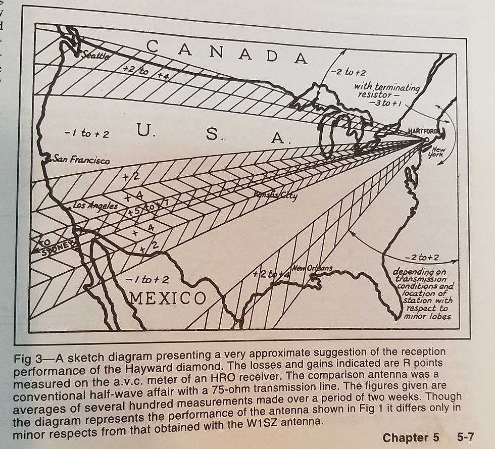
For day-to-day use of the antenna in amateur radio service, remember amateurs are not point-to-point shortwave broadcasters, military or wire-services. Amateurs just want to make QSOs!
People say the the
The rhombic suffers from efficiency problems due to ground losses, significant power-wasting spurious lobes, termination losses, and the inability to maintain constant current along the length of the conductors. Typical radiation efficiency is in the order of 50%.
However in reality a properly designed rhombic can have some of the best efficiency of any HF antenna in use today.
The ground lost can be resolved by getting the antenna over a half and better a full wavelength high on the lowest planned usable frequency. Any directional antenna functions this way, the higher up you go your ground losses go down, and you achieve up to 6 db of gain on a typical Beam by mounting it that high off of the ground also.
The spurious lobes are not really wasting power for amateur radio use some high angle can be a blessing for closer in contacts.
The main issue the terminating resistors can be eliminated through an re-entrate system, sometimes called rephrasing, which is used at the K0UO site. The system brings the efficiency to 90% or better.
Now you have very high gain low cost with the ability to withstand major storms with ease
Also most amateur radio operators don't have tens of thousands of dollars to spend on tall towers and stacked mono-band beams, or the ability to climb and maintain such structures. Rhombic antennas were the ultimate antenna design back in the Golden Age of Wireless. However, building one required a large tract of land and a lot of tall power poles, because they have dimensions several times the wavelength. To amateurs the positive thing is there are no large mono-band yagi antennas to maintain, or rotators to fix, and rhombics allows for instantaneous direction and band switching. They normally can be installed at very low cost, if you have trees to hang them from, all that is needed is a lot of wire and time!
I have four 40 meter resonant designed Rhombic traveling wave antennas in use, most use +2500 foot of cable each, for the antenna.
The key concept with traveling-wave antennas is that there are no standing waves, which means that the current and voltage levels are the same everywhere along the antenna conductors. So the Rhombic antenna does have the very distinct advantage of working over very wide frequency ranges with flat SWR and high gain.

A V Beam (Vee) is just 1/2 of a Rhombic

Above is a control box used at K0UO, with a 12 to 1 current balun with lightning protection, this box was used at the W7YRV Rhombic site of Roy Callison's

USSR
Grigory Zakharovich Ayzenberg (Григорий Захарович Айзенберг, 1904–1994) was a monumental figure in Soviet radio physics and the chief architect behind the USSR’s global shortwave and military antenna infrastructure.
The Prolific Author: He held 53 Soviet author certificates (patents) and published over 60 core scientific works. His definitive textbook series, including "Shortwave Antennas" (Коротковолновые антенны) and "Ultra-Shortwave Antennas" (Антенны ультракоротких волн), became the literal bibles for Soviet communications engineers.
Mastering Traveling-Wave Antennas: While Western designers focused heavily on resonant aluminum beams (like Yagis), Ayzenberg mastered wire arrays that leveraged traveling waves (Rhombics, V-Beams, and Fishbone arrays). He engineered the transition from single-wire systems to multi-wire "curtain" configurations to lower high-impedance loads, stabilize SWR, and widen operating bandwidths.


Many of the Rhombic insulators are from W6AM's station (which were found at the TRW Southern California parking lot sale years ago).
OVERVIEW of all the K0UO pages: The Rhombic antenna is a wide-band progressive traveling-wave (fast-wave) antenna, V-beams, Receive Directivity Factor (RDF) towers, VOA, W1AW, W6AM, Beverage traveling wave antenna, HF curtain, Broadcast tower, ham radio, balun for matching, IEEE, terminating resistor, E and H field, far field modeling, antenna measurements, NEC2 NEC4, k0uo, wire antennas, Curtain antennas, baluns, VOA sites, LPDA, W6AM, W7URA, Feed-lines, and 4KS Walz public Airport at Kiowa, KS.
Welcome to K0UO.com, where we dive into the world of rhombic, curtain, and Vee Beam antennas at the 4KS Public Airport near Kiowa, KS. Explore the intricate world of rhombic antennas, Receive Directivity Factor (RDF) towers, Beverage traveling wave antennas, and so much more. Join us as we delve into the fascinating realm of antenna farming and ham radio technology, if your group has a school or University antenna or aerospace research STEM program, let me know.


The KØUO Rhombic Antenna Farm and Test Range: Home to the World's Largest amateur radio (ham), High Frequency (HF) Wire Antennas.
For Design see
K0UO G Mail Blog
SEE K0UO's CURTAIN PAGE, even more gain than a rhombic https://www.k0uo.com/post/current-distributed-feed-system-as-used-on-sterba-curtains-will-be-utilized-on-the-new-antenna
K0UO has years of expertise in contesting, DXing, using cutting-edge technology, and engineering. The site also uses many very high-gain directional stacked and phased LPDA- beamed at all continents, large 160 -40 meters four square verticals, stacked of rhombics, V-beams, and curtain arrays, at this world class station for increased gain and better performance on all the amateur bands.

SEE Patents for Rhombic: US2517238A - Radiating termination for a rhombic antenna - Google Patents
A good read, Big and Old 27dB antenna, https://wtfda.org/wp-content/uploads/mem/rhombic.pdf
Traveling Wave Antennas Simplified https://www.youtube.com/watch?v=nPMk4pFBsWc
2 meter rhombic: @ https://www.youtube.com/watch?v=5XNaXZ2qz4Y
SEE:
Edmund Laport's "Radio Antenna Engineering", published by Mcgraw-Hill in 1952
Navy design book on rhombics. This may very well be a Navy'ized version of the War Department document (TM11-2611)
16 Rhombics https://www.youtube.com/watch?v=-z5O1LHEFlc
The 1945 Army rhombic book
A. E. Harper, "Rhombic Antenna Design", CY 1941
General Steve Walz V31KW/K0UO
TO SEE the complete Blog list check @ https://www.k0uo.com/k0uo
TIP: It is a Blog, so just SKIP the Blogs HEADER and go down to the blog.
K0UO site location @ https://maps.app.goo.gl/wDbUuTWcwZXBEZik9
Steve's Group https://en.wikipedia.org/wiki/RSI_Corporation


Mình có lần lướt đọc mấy trao đổi trên mạng شيخ روحاني thì thấy nhắc nên cũng tò mò mở ra xem thử cho biết. Mình không tìm hiểu sâu جلب الحبيب chỉ xem qua trong thời gian ngắn để quan sát bố cục جلب الحبيب cách sắp xếp شيخ روحاني các mục và trình bày nội شيخ روحاني dung tổng thể. Cảm giác là các phần được trình bày khá gọn, các Berlinintim mục rõ ràng nên đọc lướt cũng không bị rối Berlinintim với mình như شيخ روحاني vậy là đủ để nắm tin cơ bản rồi. جلب الحبيب
👍
CoffeeMasterHub explains brewing techniques in a way that is both informative and engaging.
Rural properties often have mature trees that require extra attention over time. Finding a dependable tree trimming service near me gives property owners confidence that branches are managed safely while preserving the natural beauty of the landscape.
Unbelievable achievement in putting up all of those large monster big gun antennas on your 1200 acre site. Anyone wanting information needs to read all the blog Pages you have, there is a ton of stuff, thank you
Some of the best real world information I've ever seen. This guy has really done it, he's not just modeling and theorizing he's building and using them. A Very impressive construction project