


Baluns, a VOA 200,000 watt and others
- skylarkcolo

- Nov 17, 2021
- 5 min read
Updated: Feb 26


"K0UO, Miles of WIRE, in the AIR, and ON the AIR daily"
I plan on using the BIG VOA, this is a part of Rhombic Antenna history, it needs to be "On the AIR"  Update, in 2023 it was put on back on the air on the N/S antenna UPDAT: 200 5a photo with a view of many ham radio large baluns for use on V beam and rhombic arrays

Update: 2025 now in use at K0UO's vertical polarized 1/2 Rhombic antenna

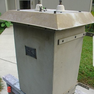
Below is a 10KW DXE Balun, and the Big 200,000 watt VOA unit, side by side!

Below is an assortment of of baluns used in amateur radio

Below: This data shows general info for the 555 and the 543 models, my Balun must be a special made for the VOA unit a 12:1 like the 543, but 600 ohm


A DOD Balun made by TMC
Here are some links to the better 12:1s that I have used for the Rhombic and Vee beams,

DXE 12:1 is not available any longer
Also: Collins numbers are: (1) 754-9057-001 and described as "1KW Termination Kit" 2) 774-6261-001 " 3) DAA805-68-C-0020 " "Transformer, Radio Frequency /TF506/TRC-136" 4) 758-5322-001 " "50-600 ohm Balun", 7649858-001 also labeled - 764-9604-001-D with "REV B" one - 764 9058 001 with "REV C"
Balun Design, only makes a 9 to 1 Unun, he will not make a 12:1

Below: Is one of my antenna control and balun boxes, that is over 1000 feet from the shack, feeding two antennas. With provisions to add one more. Using DXE 12:1 baluns, with 10 amp switching relays, and spark gap for static and lightning protection.
I use 12 volt relays, powered by solar and a deep cycle battery


You could use an exponential taper feed as a 1:4 balun, to convert the 50 Ohms unbalanced to 200 Ohms balanced. I conducted some research on "tapered lines", the findings of which are detailed below. After testing several prototypes at my K0UO test range, I decided on the tapered 2-wire transmission line, which is a modified exponential taper. The exponential feeder is used to match (not tune) the antenna's feeding end. It acts as a broadband linear transformer from 900 ohms to 200 ohms. Essentially, it's an economical broad-banded transformer. As suggested, there is an exponential feedline at both the feed end and the termination end. The exponential feedline ensures the correct impedance across the entire useful frequency range of the rhombic. For the higher band, use a 20m long tapered open wire feed line, beginning with a spacing of 10 mm and expanding to 300 mm at the end. The taper is designed logarithmically, but a linear taper would also suffice. The key is that it should be at least 1 wavelength at your lowest frequency.

A tapered feed system for a rhombic antenna is a method of impedance matching that gradually transitions the feed-line impedance to the rhombic antenna’s input impedance. Because rhombic antennas have very high, frequency-dependent impedances (often 600–800 Ω or more), a direct connection to a standard transmission line (50, 75, or 300 Ω) would cause severe mismatch and reflections. The “taper” allows RF energy to smoothly transition from one impedance to another with minimal reflections, similar to a tapered waveguide or a transformer with many tiny steps.
A tapered feed system is a gradually changing impedance transmission-line section used to match standard transmission lines to the high input impedance of a rhombic antenna. It ensures broad bandwidth, good SWR, and low reflections.
Exponential taper (most popular due to wide bandwidth)
Linear taper
Klopp or “Klopfenstein taper”
Matches the line impedance to the antenna input
Smooths impedance variations over a wide bandwidth
Improves VSWR
Maintains the rhombic’s inherently broadband performance

You can also stack rhombics with an exponential matching section, they are connected between the mid point of the stacked rhombics and the feeder at an angle to the horizontal, with a flying spreader at the mid point in the line. The impedance measured at the 600 ohm feeder input of a four element rhombic array.The output impedance of a stacked pair of rhombics is approximately 300 ohms and this must be matched over the operating frequency range to the 600 ohm feeder. The interlaced rhombic array requires three 300 to 600 ohm matching sections. The wide-band impedance matching properties of exponential lines are well known., but not used by many hams,
You could also do this to terminate the antenna, to a 50 ohm high power dummy load can, since large high-power non-inductive power resistors are so hard to find and cost big $$$$s. Use a 16:1 or 12:1 balun to a 50 ohm power resistor (rated a 33 to 50% of the input power), or you could use an exponential taper feed with a1:4 balun, to transform the 600 to 800 ohm unbalanced to 50 Ohms balanced termination.
Also your antenna will need a Ladder line static bleeder of some type.
DXE has one also, see
below


Above: Using a spark gap for static and lightning protection which also protects your terminating resistors. it is a good safety precaution.


The K0UO antenna test range site makes use of the 4KS Walz airport and its surrounding area as a practical learning environment for STEM (Scientific, Technical, Engineering, & Mathematics) antenna projects in a real-world outdoor setting. If your group has a university aerospace or antenna research STEM program, please let me know.

The KØUO Rhombic Antenna Farm and Antenna Test Range: Home to the World's Largest amateur radio (ham), High Frequency (HF) Wire Arrays, miles of wire in the air and on the air daily.


Comments