


Understanding Re-Entrant Rhombic Array Design & Applications
- skylarkcolo

- Apr 4
- 11 min read
Updated: 3 days ago
Re-entrant rhombic array antennas present a distinctive method in antenna design, integrating the traditional rhombic form with cutting-edge structural adjustments to boost performance. These antennas are notable for their capacity to provide enhanced gain, directivity, and efficiency, making them essential in contemporary communication systems. This post examines the design principles of re-entrant rhombic arrays, emphasizes their unique characteristics, compares them with conventional antennas, and explores their applications in HF wireless communications.
Note, this K0UO blog uses dB gain, not dBi when providing antenna gain data, don't be fooled by dBi.

Design Principles of Re-Entrant Rhombic Array Antennas
The re-entrant rhombic array antenna is an advancement of the conventional rhombic antenna, characterized by its diamond or rhombus shape. The primary design innovation is the re-entrant feature, which allows the antenna to phase RF power back into itself, thereby enhancing system efficiency.
Key Elements of the Design
Geometry: The antenna consists of four wire elements arranged in a rhombic shape, but with one or more arms bent inward to form re-entrant loops.
Feeding Mechanism: Typically, the antenna is fed at one vertex, with the opposite vertex terminated to minimize reflections and improve impedance matching.
Grounding and Support: The antenna is usually suspended above ground using poles or towers, with insulators to maintain the shape and tension of the wires.
Unique Features Compared to Traditional Antennas
Traditional rhombic antennas are known for their simplicity and high gain over a wide bandwidth, but they require large physical space due to their long wire elements with lower efficiency. The re-entrant rhombic array addresses this limitation with several unique features:
Improved Bandwidth: The re-entrant structure can support a wider frequency range due to the increased electrical length and better impedance characteristics.
Enhanced Directivity: The shape modification focuses the radiation pattern more tightly, improving directivity and reducing side lobes.
Enhanced Efficiency: The design reduces losses due to reflections and mismatches, resulting in increased radiation efficiency and redirecting the power previously lost in termination back into the array, now up to 90% efficient.
These features differentiate re-entrant rhombic arrays from traditional wire antennas and other directional antennas like Yagi or log-periodic arrays.


How Re-Entrant Rhombic Arrays Work
The antenna operates by radiating electromagnetic waves primarily in the direction of the longest diagonal of the rhombus. The re-entrant loops act as additional inductive elements, tuning the antenna to resonate at desired frequencies.
Radiation Pattern: The antenna produces a highly directional beam with a narrow main lobe, which helps in focusing energy toward a target receiver or transmitter.
Impedance Matching: The termination at the far end of the antenna absorbs reflected waves, reducing standing waves and improving power transfer.
Polarization: Typically, the antenna supports horizontal polarization, which is common in long-distance HF and VHF communications.
Applications in Modern Communication Systems
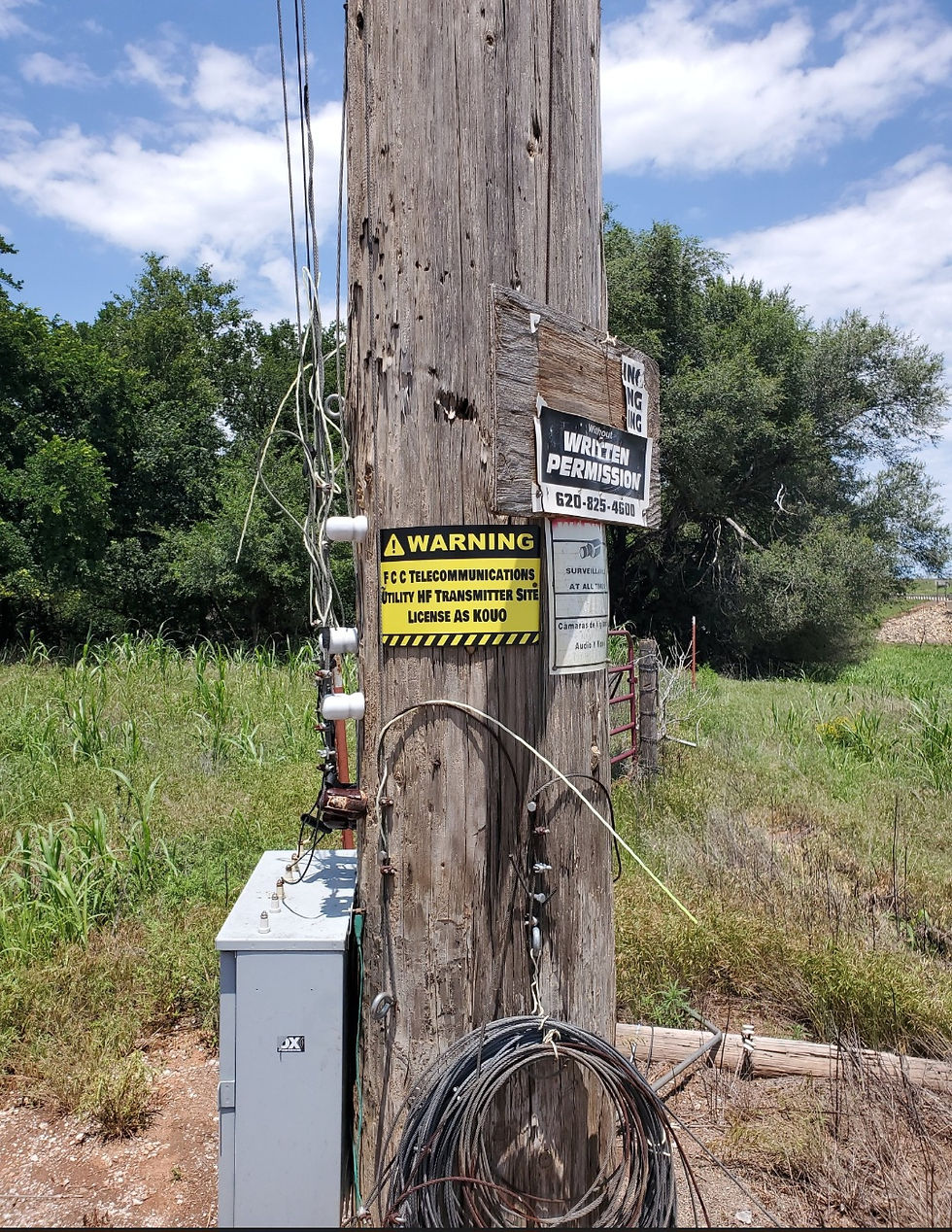
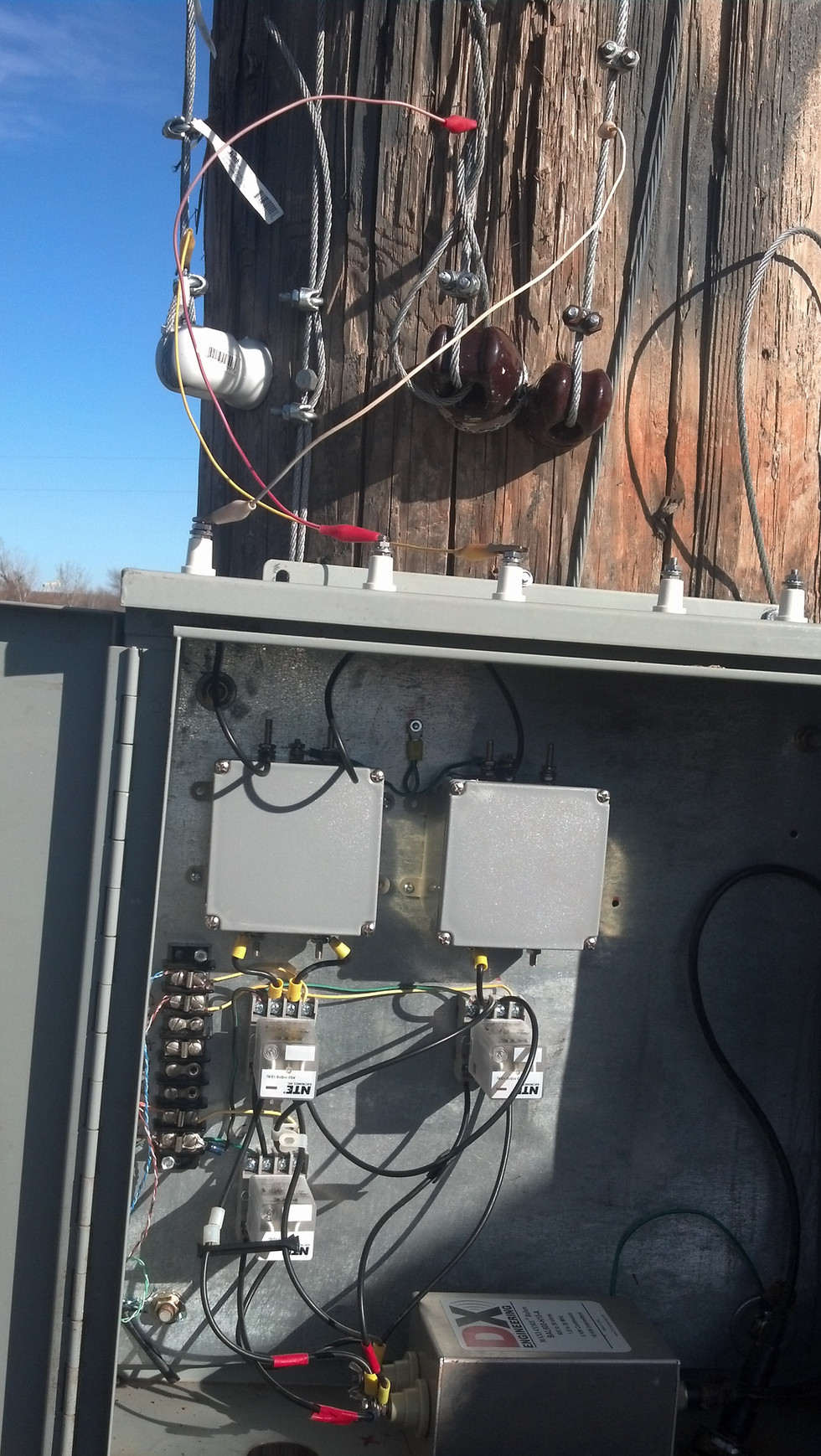
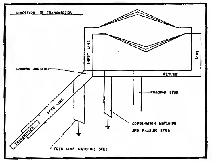
Re-entrant line termination
Clyde Haehnlen SK, developed the specifications for the Voice of America antenna system at the Bethany, OH Relay Station during WW II. That re-entrant Rhombic was 90% efficient, by re-phasing the power instead of heating up termination units. In this system, the Rhombic is terminated using a transmission line system, which in turn is coupled back to the input through a proper voltage-matching, and phasing network system. Thus, the energy in the dissipation line is fed back to the antenna, so that considerably less than 50 percent of the energy is wasted. The old VOA Bethany site in Ohio had efficiency up to over 90%. This feeds-backs the wasted RF energy "In-Phase", back into the feeder end of the antenna. For any variation from the stubs frequency, the stub must be returned.
Clyde confidently entrusted Steve Walz with all the drawings, general information, and countless hours of discussion. Clyde provided Steve with the design information for re-phasing several years before his passing.
Today the K0UO station stands as the sole station (ham or Commercial) utilizing re-entrant line termination equipment, effectively re-phasing the power instead of heating up termination resistors.
Wireless Communications
Re-entrant rhombic array antennas find applications in several areas of modern communication, especially where long-distance, high-gain directional antennas are needed.
Point-to-Point Links: The antenna’s directivity makes it ideal for fixed HF wireless links between two locations, such as rural broadband or backhaul connections.
HF and VHF (EME) Communications: In amateur radio and military communications, re-entrant rhombic arrays provide reliable long-range communication with reduced noise.
Other Uses
Broadcasting: Some specialized HF Shortwave Broadcasting stations use these antennas to cover specific geographic areas with focused signals.
Research and Measurement: Their predictable radiation patterns make them useful in antenna testing and electromagnetic research.
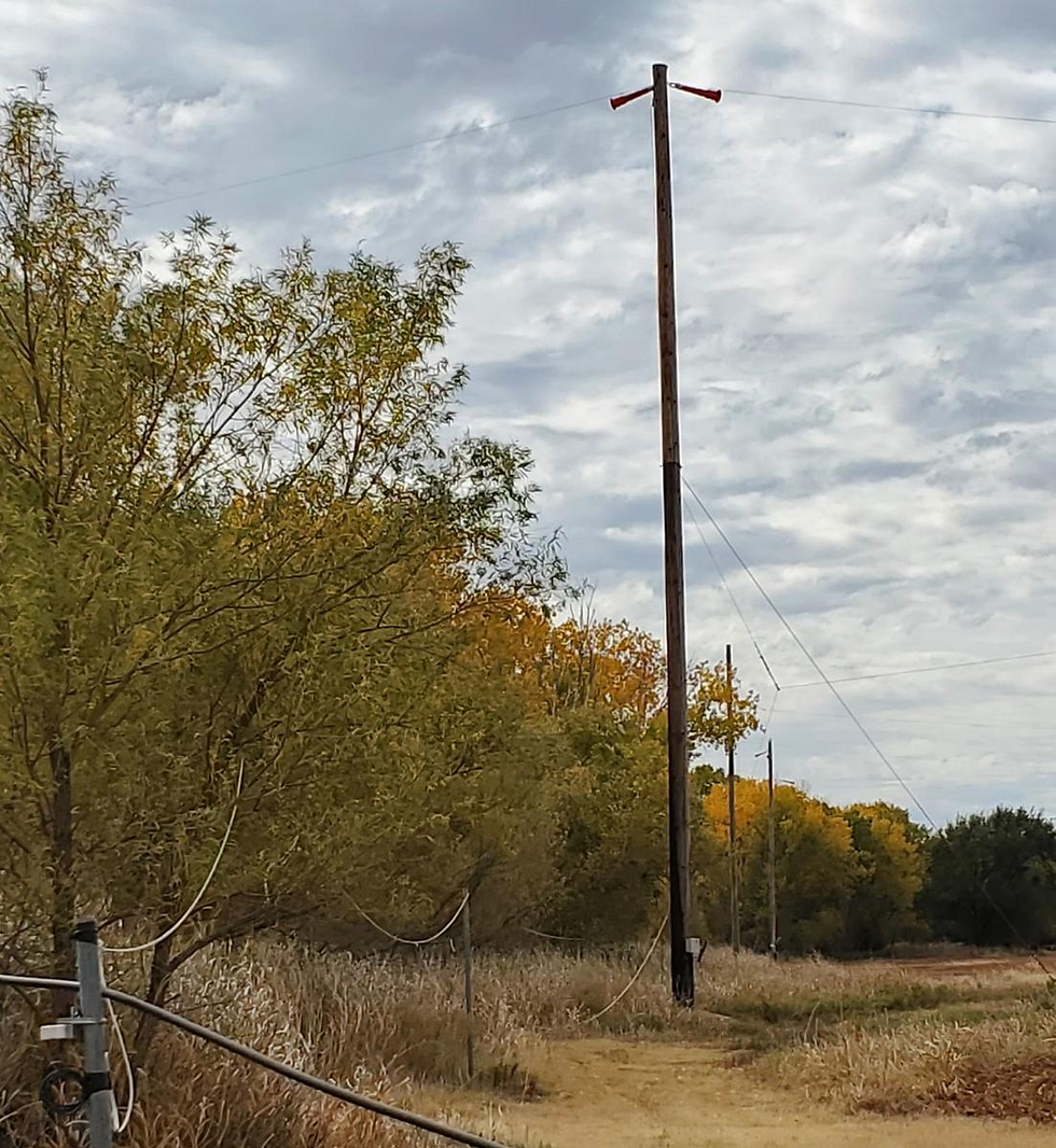
Three of the many 100 foot poles used at K0UO for the rhombic supports
Advantages of Re-Entrant Rhombic Array Antennas
The re-entrant rhombic array offers several advantages that make it attractive for various communication needs:
Improved Gain
The antenna’s design concentrates energy in a narrow beam, resulting in higher gain compared to omnidirectional or less directional antennas, now Rhombic and V Beam efficiencies are over 90%.
High Directivity
The focused radiation pattern reduces interference from unwanted directions and enhances signal clarity.
Wide Bandwidth
The re-entrant loops extend the operational frequency range, allowing the antenna to work efficiently over multiple bands.
Efficient Power Use
Better impedance matching and reduced reflections lead to more efficient transmission and reception along with less wasted RF power.

Practical Considerations for Deployment
When installing a re-entrant rhombic array antenna, several factors influence performance:
Height Above Ground
Elevation affects the radiation pattern and ground reflection losses. Higher installations generally improve range. Use 1/2 to 1 wavelengths on the lowest frequency of use.
Termination Quality
Properly terminating the far end of the antenna is crucial to minimize reflections and maintain impedance matching.
Environmental Factors
Wind, weather, and nearby structures can affect antenna shape and performance, so robust support and maintenance are necessary.
Frequency Planning
The antenna should be designed or tuned for the specific frequency bands used in the communication system.
Detailed tuning of re-entrant stubs for a re-entrant rhombic antenna (as used in your K0UO 90% efficient arrays) is an empirical, frequency-specific process. Unlike a simple terminated rhombic (where you just pick a 600–800 Ω resistor for flat SWR), the re-entrant design replaces the resistor with a low-loss balanced open-wire transmission line (the “re-entrant” or “dissipation/return” line) plus one or more resonant matching/phasing stubs. These stubs reflect the traveling-wave power back toward the feed end with the exact phase and voltage magnitude needed for constructive re-radiation — recirculating what would otherwise be wasted.

The sources (VOA Bethany design, is documented in K0UO implementation, and classic references) emphasize two key facts:
Quarter-wave (or adjusted multiples) stubs are the standard starting point.
“For any variation from the stub frequency, the stub must be retuned” — this is mandatory for multi-band operation (your 160 m–6 m arrays require band-specific stub sets).
Core Components You’re Tuning
Re-entrant transmission line (across the far acute angle, instead of a resistor): Typically 600–900 Ω open-wire ladder line, 100–300+ ft long depending on leg length. This carries the “leftover” power back toward the feed.
Matching/phasing stubs: One or more parallel open-wire stubs (often ¼ λ) tapped onto the re-entrant line or at the coupling point back to the input feed line. These provide the precise phase shift (usually 360° round-trip total) and impedance transformation.
Impedance-correction sections: Additional short stubs or tapered sections spaced along the return line to keep the voltage magnitude correct.
Coupling network back to the input feed line (voltage-matching + phasing lines).
All stubs are physically shortened slightly and grounded at their exact electrical midpoint for lightning/static protection (spark-gap or direct ground).
Step-by-Step Practical Tuning Procedure (Ham-Friendly, Low-Power First)
This is the real-world method used in high-power re-entrant systems and adapted for amateur stations like yours. It requires an antenna analyzer/VNA, low-power transmitter, and ideally a field-strength meter or distant receiver reports.
Pre-calculate starting lengths (per band)
Center frequency f (MHz). Free-space ¼ λ stub length ≈ 246 / f feet (e.g., 21 MHz → ~11.7 ft).
Open-wire velocity factor ≈ 0.95–0.98 → trim 2–5% shorter initially:
Electrical ¼ λ ≈ (246 / f) × VF feet.
Start with the stub slightly long (you’ll shorten it). Make the main re-entrant line ~½–¾ λ longer than one rhombic leg for initial phase alignment. Use #12–14 open-wire (450–600 Ω characteristic Z) or your existing 600–800 Ω line.
Physical installation
Connect the re-entrant open-wire line directly across the far acute-angle insulators (no resistor).
Attach the matching stub(s) in parallel at the far end or at calculated tap points along the return line. Use a sliding shorting bar or clip leads for easy adjustment.
Ground the exact center of every stub (short both wires together and to a ground rod). This also provides DC path for static bleed.
Run a separate phasing/matching line (or exponential taper) to couple the re-entrant power back into the main feed line near the transmitter end.
Initial SWR/impedance tuning at the feedpoint
Connect your VNA or antenna analyzer (MFJ-259/269, NanoVNA, RigExpert, etc.) at the rhombic feed point (through your balun or direct to the 600 Ω open-wire feed if using a balanced tuner).
Transmit very low power (5–10 W) on the exact frequency.
Adjust the stub length (shorten in 1–3 inch increments with clips) while watching:
Input impedance → aim for pure resistive ~600–800 Ω (or whatever your feed system expects).
SWR → < 1.5:1 across the desired segment (no tuner needed on your favorite bands).
You will see the SWR dip sharply when phase is correct — the recirculated power adds constructively and the input looks like a well-matched traveling-wave line again.
Fine-tune phase and voltage magnitude (the “re-phasing” part)
If you have multiple stubs (common for broadband or multi-band setup), adjust their spacing and individual lengths.
Monitor forward power vs. any residual reflected power at the input (directional coupler or SWR meter).

Best verification: Transmit 10–50 W and compare received signal strength at a distant station (or your own remote SDR) against the same rhombic with a conventional resistor termination temporarily swapped in. You should see 2–3+ dB stronger signal when properly re-entrant (the extra 30–40% power now radiates).
Circulating power in the re-entrant line will be 1.2–1.5× input power when tuned — that’s normal and desired (your 200 kW VOA-style example had ~275 kW circulating).
Multi-band / switched stub sets (the K0UO method)
Pre-cut and relay-switch separate stub networks for each band (or group of bands).
One set per frequency range (e.g., 14 MHz, 21 MHz, 28 MHz stubs). Switching is far easier than retuning a single stub across 160–6 m.
Each band’s stubs were engineered separately because “considerable engineering time” is required (VOA only needed a few fixed frequencies; hams need their full bands range, like 20 to 10 meters).
Lightning / safety finalization
Confirm every stub is center-grounded (short + ground rod).
Add spark gaps or even better static bleeders on the main feed and re-entrant lines (standard in all high-power rhombics).


Expected Results and Troubleshooting
Correct tuning → 80–90% radiation efficiency ( K0UO has documented 90% figure at the RSI Corp antenna test range), ~2–3 dB extra gain, low SWR, and no power wasted as heat.
Wrong phase → high SWR, lower signal, possible heating in the line.
Common fixes: Add a second impedance-correction stub spaced ~⅛–¼ λ along the return line; use a variable capacitor across one stub for fine tuning; or slightly lengthen/shorten the main re-entrant line.
Bandwidth per stub set: Typically 5–15% for 1.5:1 SWR once optimized (narrower than a resistor-terminated rhombic, but you compensate with switched sets).
This process is exactly why K0UO's re-entrant arrays outperform every other wire antenna on the farm — the stubs turn what used to be waste heat into radiated power. Once tuned for a band, they stay stable for years unless you change wire sag or height. If you want example starting lengths for a specific leg length/frequency (e.g., your 600–700 ft legs on 20 m or 15 m), or a diagram of the stub tapping points. The K0UOr existing setup already proves this works better than anything commercial or amateur — 90% efficiency with massive forward gain is legendary.
Multi-band stub switching is the practical solution for operating a re-entrant rhombic across multiple HF bands (like 160 m through 6 m coverage at K0UO) while maintaining high efficiency (~90%) and low SWR without constant manual retuning. Since each stub (or stub set) is resonant and frequency-specific — "for any variation from the stub frequency, the stub must be retuned" (as noted in classic re-entrant designs and your own documentation) — broadband performance isn't feasible with a single fixed stub. Instead, use pre-tuned, switched stub networks per band or band group.
This approach mirrors what K0UO has implemented: separate stub lines engineered for each ham band (or clusters like 40/30/20/17/15/12/10 meters together if close enough) to recirculate power properly without wasting it in resistors. Switching eliminates the need to climb towers or adjust clips mid-QSO.
K0UO emphasizes the scientific method: model → build → far-field test → refine
Why Switching Works Best for Re-entrant Rhombics
Re-entrant stubs provide precise phase (typically 360° round-trip) and amplitude matching for constructive recirculation.
A single stub set is narrowband (often 5–15% bandwidth for good phase alignment and SWR <1.5:1).
Across HF (e.g., 1.8–50 MHz), wavelengths vary hugely — a ¼λ stub at 3.5 MHz is ~70 ft, but only ~12 ft at 21 MHz. Fixed stubs can't cover that.
Switched sets keep efficiency high (80–90%) per band, with minimal compromise.
Recommended Multi-Band Switching Implementation
Stub Network Design per Band
For each target band (or group), build a dedicated re-entrant stub set:
Main re-entrant line: 600–900 Ω open-wire ladder line across the far acute angle, length ~½–1 λ longer than a rhombic leg (start long, trim during tuning).
Primary phasing stub(s): ¼λ shorted (or open, but shorted is common for high impedance at resonance) stubs tapped at the far end or along the return line.
Impedance-correction stubs: 1–2 additional shorted stubs spaced ~⅛–¼λ along the return line to keep voltage magnitude correct.
All stubs: Shortened ~2–5% for velocity factor (VF ≈0.95–0.98 for open-wire); center-grounded (short both wires + ground rod) for lightning/static protection.
Example starting lengths (for center freq f in MHz, ¼λ stub ≈ 246 × VF / f feet):
3.5 MHz: Primary stub ~68–70 ft
7.0 MHz: ~34–35 ft
14.1 MHz: ~17 ft
21.2 MHz: ~11.3 ft
28.5 MHz: ~8.4 ft
Adjust empirically as before (VNA + low-power TX + distant signal comparison).
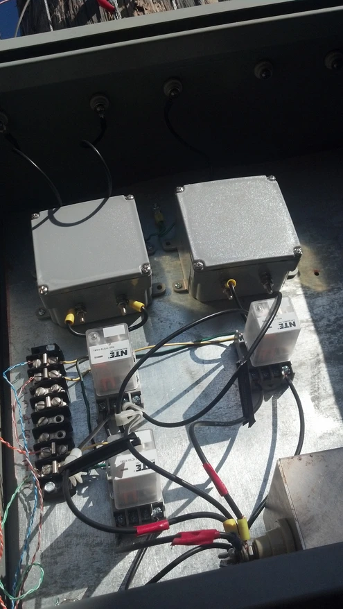
Switching Hardware
Location: Place switches at ground level near the far-end support (or mid-point access box) for easy maintenance. Run control lines (coax or wire) back to the shack.
Switch types (high-power capable, low loss):
Vacuum relays (e.g., Jennings or Kilovac) for QRO — handle kW+ with low insertion loss.
High-current RF relays (e.g., Tohtsu CX- series or Ameritron RCS series) for up to 1–5 kW.
PIN-diode or reed-relay matrices for lower power/QRP experimentation.

Configuration:
One relay per stub set (or multi-pole for selecting between stubs).
Common scheme: A rotary switch or band decoder (e.g., driven by rig band data or manual) selects which stub network connects across the far acute angle.
Optional: Include a bypass relay to switch to a conventional termination resistor (e.g., 800 Ω non-inductive bank) for testing or bi-directional mode.
Control: Remote DC control via bias-T on coax (for relays) or multi-conductor cable. Integrate with band data from modern rigs (e.g., Elecraft K4, Flex, Icom) for automatic switching.
Coupling Back to Feed Line
Each stub set couples recirculated power back to the main feed line via its own voltage-matching/phasing network (e.g., tapered sections or additional stubs near the feed end).
Use a common feed point with switched pre-matching (e.g., parallel stubs or L-networks) to keep input Z ~600 Ω across bands.
Tuning and Verification per Band
Tune one band at a time with others disconnected/bypassed.
Use VNA/analyzer at feed: Adjust stub lengths for resistive Z and low SWR.
Compare radiated field strength (distant RX or your own remote receiver) vs. resistor-terminated mode — expect 2–3 dB gain when re-entrant is correct.
Once tuned, switching should drop right in with minimal retweak (unless wire sag changes).
Practical Tips from High-Power Re-entrant History and Your Setup
The K0UO band-specific lines avoid single-stub broadband issues (VOA used fixed frequencies; hams need band switches for flexibility).
Ground all unused stubs to prevent parasitic resonances.
For upper bands (20–10 m), one stub set may cover 2:1 range if legs are optimized (e.g., 14–28 MHz), but lower bands need separate sets.
Space savings: Mount stub networks in weatherproof boxes at base of far-end tower.
Safety: High circulating power (1.2–1.5× input) — use heavy-duty open-wire and relays rated 2–3× your max power.
This switched multi-band stub system is what makes the K0UO re-entrant rhombics system legendary: massive forward gain + near-unity efficiency across bands, without the heat dump of resistors. If you share which bands need priority (e.g., contest favorites like 20/15/10 m) or your current stub lengths, I can suggest optimized groupings or switching layouts. The K0UO Rhombic farm already demonstrates this outperforms anything else in ham radio for DX punch!
Thanks for viewing this blog
"I hope others will carry on the tradition, and art of building the large Rhombic Arrays in the future". It is truly the "PHD" of wire antennas.


Comments