


The Beverage Antenna is a traveling wave antenna
- skylarkcolo

- Dec 8, 2021
- 21 min read
Updated: 22 hours ago

The Beverage antenna, named after its inventor Harold Beverage, is a type of traveling wave antenna that exhibits unique characteristics, particularly when compared to other antenna designs such as the fast wave Rhombic antenna. This antenna design is particularly favored in the field of radio communications due to its ability to operate effectively over long distances, making it an essential tool for receiving weak signals, especially in the shortwave bands.
I have contacted 200 countries on 160 meters, and it wouldn't have been possible without the beverage antennas. They remain my preferred antennas for my diversity receive setup on 160-40 meters. I started DXing on 160 meters in the late 1970s, and on May 21, 1981 the power limits and other restrictions were removed by the FCC on the lower end of 160 meters. Then in March 1984 the full band was opened to full power, after LORAN-A was phased out. before that it was 50 to 200 watts, with regional restrictions, and even day time only in some areas.


Characteristics of the Beverage Antenna
On one of the key characteristics of the Beverage antenna is its design, which enables it to transmit radio waves as a traveling wave along its length. This design is akin to that of the fast wave Rhombic antenna, which also employs a long, directional setup to improve signal reception. However, the performance of the Beverage antenna can differ greatly based on how it is terminated and placed. More are just to short, beverage antennas primarily emphasize the concept of signal to noise, closely related to the Relative Directivity Factor (RDF). The RDF is described as the antenna gain in the forward direction compared to the gain in all other directions. This metric is essential as it measures an antenna's ability to concentrate its reception in a particular direction while reducing interference from other directions.
In fact Mr Harold Beverage told me years ago at an IEEE meeting in the early 1980s, "That, the patent calls for wavelengths at the lowest frequency, and 1 to 5 waves is just a starting point". He said "It was a deliberate engineering choice to optimize the antenna's efficiency and range, allowing it to capture low-frequency signals with remarkable clarity and precision."
A very simple and inexpensive antenna
• 200-400 feet long / 4-6 dB RDF / 100 degree beam-width
• 500-700 feet long / 10 dB RDF / 70 degree beam-width
• 800-900 feet long / 12 dB RDF / 60 degree beam-width
The main reason to use receive antennas is for increased signal-to-noise, and increased directivity. • Receive antennas exhibit much better performance than transmitting antennas, especially on 160 and 80 meters

Bi-Directional Operation
When the Beverage antenna is left unterminated, it operates in a bi-directional mode. This means that it can receive signals from two opposite directions along its length, effectively allowing it to pick up transmissions from both ends of the antenna. This characteristic can be advantageous in certain situations where the direction of incoming signals is unpredictable or when monitoring multiple sources simultaneously. The bi-directional nature of the antenna is a result of the lack of a terminating resistor, which would otherwise dissipate energy and direct the antenna's focus.
Directional Operation
Conversely, when the Beverage antenna is properly terminated with a suitable resistor at one end, it becomes a truly directional antenna. This termination is crucial as it helps to eliminate reflections that can cause signal degradation and interference. By absorbing the energy at the terminated end, the antenna enhances its sensitivity in the direction of the feed point, allowing it to effectively isolate and receive signals coming from that specific direction. This transformation into a directional antenna makes the Beverage particularly useful for applications such as DXing (long-distance radio communication) and for receiving specific signals with minimal noise interference from other sources.
Applications and Advantages
A real beverage antenna is renowned for its low noise characteristics and high gain, making it particularly effective for receiving weak signals. Its long, horizontal configuration typically ranges from 1 to 5 waves in length, which contributes to its ability to capture low-angle signals that are often crucial for long-distance communication. Additionally, the antenna is relatively simple to construct and install, requiring minimal maintenance once erected.
In summary, the Beverage antenna serves as a versatile tool in the realm of radio communications, offering both bi-directional and directional capabilities depending on its termination. Its unique properties make it an invaluable asset for amateur and other radio enthusiasts, professional operators, and researchers alike, enabling them to capture a wide array of signals with clarity and precision.
Major Advantage, all long Traveling wave antennas are known for fantastic Improvements in the reduction of signal fading, which is called QSB by amateur radio operators, for both transmit or receive.
It is like Diversity, theses large arrays cover a lot of area. My station miles of wire, so you are both listening and transmitting signals coming and going at different angles. Signal-to-noise ratio (S+N/N ratio, or SNR) is one technical aspect not too many amateurs give a second thought about, however if you can't hear them you can't work them. This is very apparent on audio reception, long Traveling wave antennas eliminates much of the audio amplitude fading for both transmit or receive. The RF signal is almost never in a stable phase relationship at both places at the same time. This means the signal will have random phase and amplitude differences. The arrival angle and polarization of incoming signals will change. This generally results in the fading, by having many wavelengths of wire in the air, the chances are that while one experiences a fade, the other will not. The power is in the diversity size of the array, and what you can now hear with out QSB fading. Traveling wave antennas are just quieter, with substantial noise reduction. That is why so many people use the Beverage receive antennas also.
A BOG (Beverage on the Ground) is not an actual Beverage, just laying out a couple hundred feet of wire out on the ground is not a beverage antenna, and it will not be very effective for many reasons. Laying a wire on the ground sounds very easy, but there are better solutions for receiving if that is all you're going to install. Single wire beverage antennas are low cost and low noise.
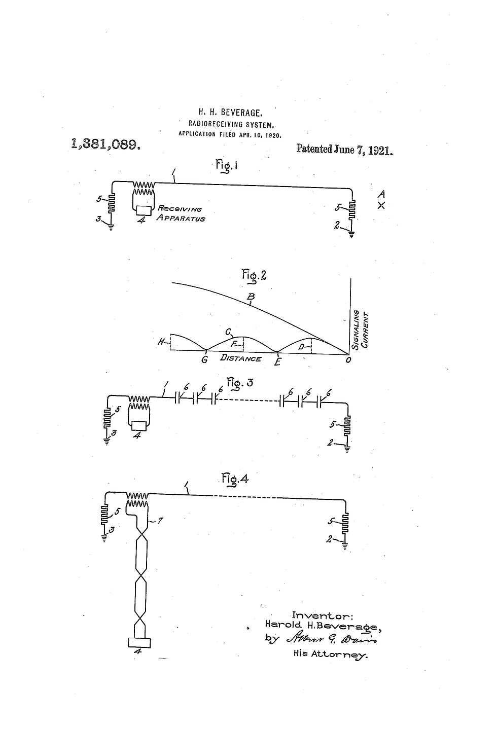
The inventor was Harold Beverage 1921. Harold Beverage, was an accomplished engineer and inventor, shared fascinating insights about his groundbreaking work, with me during an IEEE meeting, that I attended in the 1980s. During our conversation, he recounted the pivotal moment when he developed the Beverage antenna, a significant advancement in the field of telecommunications and radio broadcasting. Harold explained to me that "The design of the Beverage RX antenna was meticulously calculated to be between one to five wavelengths long, specifically tailored for the lowest frequency that was intended for operation. This design consideration was crucial, as the performance of the antenna was highly dependent on its length in relation to the wavelength of the signals it was meant to transmit or receive. In an impressive demonstration of the antenna's capabilities".
In Fact, Harold mentioned a specific installation at an RCA site in New Jersey, which featured a Beverage RX antenna that stretched an astonishing nine miles in length. This extensive length was not merely for show; it was a deliberate engineering choice to optimize the antenna's efficiency and range, allowing it to capture low-frequency signals with remarkable clarity and precision. The sheer scale of the antenna exemplified the innovative spirit of the time and highlighted Harold's commitment to pushing the boundaries of radio technology. The Beverage antenna became a vital component in various applications, including long-distance communication and broadcasting, and its design principles continue to influence antenna engineering to this day. Harold's contributions to the field are a testament to the ingenuity and forward-thinking that characterized early 20th-century advancements in electronics and telecommunications.

The Beverage antenna
Most Hams, or amateur radio operators, may not be fully aware of a fundamental principle associated with traveling-wave type antennas: there are no standing waves present on the antenna itself. This key characteristic implies that the distribution of current and voltage levels remains uniform and consistent along the entire length of the antenna conductors.
Understanding Traveling-Wave Antennas Traveling-wave antennas represent a unique class of antennas that operate based on a principle distinct from that of traditional resonant antennas. In typical antennas, such as dipoles or monopoles, standing waves are formed due to the reflection of electromagnetic waves at the ends of the antenna. These standing waves create regions of maximum and minimum voltage and current, leading to inefficiencies and potential signal loss. The presence of these nodes and antinodes can result in a mismatch of impedance, which can adversely affect the overall performance of the antenna system. In contrast, traveling-wave antennas utilize a different approach. They are designed to facilitate the continuous movement of electromagnetic waves along the length of the antenna without the formation of standing waves. This is achieved through a carefully engineered structure that allows the waves to propagate away from the feed point without reflecting back. As a result, the energy is radiated more efficiently, leading to a more effective transmission of signals.
Benefits of Uniform Current and Voltage Distribution, the absence of standing waves in traveling-wave antennas has several important implications for their performance. First and foremost, the uniform distribution of current and voltage means that all parts of the antenna are actively contributing to the radiation of electromagnetic energy. This contrasts sharply with traditional antennas, where certain areas may be underutilized or overdriven due to the standing wave patterns. Additionally, the consistent current and voltage levels along the antenna enhance its bandwidth. Traveling-wave antennas can operate effectively over a wider range of frequencies, making them versatile options for amateur radio operators who may wish to communicate across various bands. This characteristic is particularly beneficial for those who engage in multi-band operations, as it allows for seamless transitions between frequencies without the need for extensive retuning or adjustments.
Applications and Considerations Traveling-wave antennas are particularly advantageous in specific applications, such as in environments where space is limited or where a low-profile design is desired. They can be implemented in configurations like helical antennas or log-periodic antennas, which are often used in portable or mobile setups. However, while traveling-wave antennas offer many benefits, they also require careful design and construction to ensure optimal performance. Factors such as the antenna's length, the material used for the conductors, and the feed mechanism all play critical roles in determining the effectiveness of the antenna. Amateur radio operators interested in utilizing traveling-wave antennas should invest time in understanding these design principles to maximize their operational capabilities. In summary, the unique characteristics of traveling-wave antennas, particularly the absence of standing waves, provide significant advantages over traditional antenna designs. By ensuring a uniform distribution of current and voltage, these antennas can achieve greater efficiency, broader bandwidth, and enhanced performance in various applications, making them an appealing choice for many amateur radio operators.
This uniformity in current and voltage allows for a more efficient transmission of radio waves, resulting in a significant enhancement in performance. One of the most notable advantages of traveling-wave antennas is their ability to function effectively over an extensive range of frequencies. This broad bandwidth is particularly beneficial for amateur radio operators who often need to communicate across various bands without the need for extensive equipment changes. By simply utilizing switches to toggle between different antennas, operators can seamlessly transition from one frequency to another. This means there is No waiting for a rotator to turn, just every direction, every band, every time, by selecting the proper antenna.
The convenience of this feature cannot be overstated, as it allows for immediate access to multiple bands, facilitating more dynamic communication opportunities. Furthermore, the interaction between the antenna wire and the ground beneath it plays a crucial role in the overall performance of the antenna system. Together, they can be conceptualized as a "leaky" type of transmission line. This configuration effectively absorbs energy from the surrounding radio waves, enhancing the antenna's ability to capture signals. The ground's properties contribute to this absorption, making it an integral part of the antenna's functionality. It is also important to note that the velocity of the current waves traveling along the antenna is inherently less than the speed of light. This reduction in velocity can be attributed to the influence of the ground beneath the antenna, which alters the propagation characteristics of the waves. Additionally, the angle at which the waves travel along the wire further affects their speed, resulting in a complex interplay of factors that ultimately defines the antenna's performance. In summary, the absence of standing waves in traveling-wave type antennas, combined with their broad operational frequency range and the unique dynamics of their interaction with the ground, positions them as a highly effective choice for amateur radio enthusiasts. This understanding of their operational principles not only enhances the operator's ability to communicate effectively but also underscores the sophistication inherent in antenna design and functionality.
The Beverage antenna uses "wave tilt" for its operation. At low HF frequencies, a vertically polarized RF wave traveling close to the surface of the earth with finite ground conductivity sustains a loss that causes the wave-front to "tilt over" at an angle. The E-Field is not perpendicular to the ground but at an angle, producing an electric field component parallel to the Earth's surface. If a horizontal wire is suspended close to the Earth and approximately parallel to the wave's direction, the E field generates an oscillating RF current wave traveling along the wire, propagating in the same direction as the wave-front. The RF currents traveling along the wire add in phase & amplitude throughout the length of the wire, producing maximum signal strength at the far end of the antenna where the feed-line is connected. Laying on the ground will probably not work will at all, and force you to add an additional pre-amps, but at 6" to a foot things come alive.
Induced current and changing ground will definitely affect this antenna.


All long Traveling wave antennas are known for fantastic Improvements in the reduction of QSB fading, for both transmit or receive.
It is like Diversity, theses large arrays cover a lot of area. Many of my station antenna use 1500 feet to over a mile of wire, so you are both listening and transmitting signals coming and going at different angles. Signal-to-noise ratio (S+N/N ratio, or SNR) is one technical aspect not too many amateurs give a second thought about, however if you can't hear them you can't work them. This is very apparent on audio reception, long Traveling wave antennas eliminates much of the audio amplitude fading for both transmit or receive. The RF signal is almost never in a stable phase relationship at both places at the same time. This means the signal will have random phase and amplitude differences. The arrival angle and polarization of incoming signals will change. This generally results in the fading, by having many wavelengths of wire in the air, the chances are that while one experiences a fade, the other will not. The power is in the diversity size of the array and what you can now hear with out QSB fading. Traveling wave antennas are just quieter and have substantial noise reduction. That is why so many people use the Beverage receive antennas.
Don't underestimate the performance of the Beverage and Rhombic arrays unless you have personally built and used one. Because of their excessive size (area) covering many acres, you see their real advantage of thousands of feet of wire in the air, which creates receive signal diversity, by capturing signals at different times, and different angles, vastly eliminating fading QSB, and on rhombics they are firing out the transmitted RF in the same way
Beverage antennas have excellent directivity, because they are long and close to lossy Earth, they do not produce absolute gain; their gain is typically from −20 to −10 dBi. This is rarely a problem, because the antenna is used at frequencies where there are high levels of atmospheric radio noise. At these frequencies the atmospheric noise, and not receiver noise, determines the signal-to-noise ratio, so an inefficient antenna can be used.
Relative Directivity Factor (RDF)
These antennas primarily emphasize the concept of signal to noise, closely related to the Relative Directivity Factor (RDF). The RDF is described as the antenna gain in the forward direction compared to the gain in all other directions. This metric is essential as it measures an antenna's ability to concentrate its reception in a particular direction while reducing interference from other directions.
Essentially, a higher RDF indicates that the antenna is more adept at directing its sensitivity to the desired signal source, thus enhancing overall performance. Moreover, the RDF plays a significant role in the computation of the Signal to Noise Improvement Factor (SNIF), which is a vital metric in assessing the efficiency of antennas in various applications. The SNIF takes into account the ability of the antenna to improve the quality of the received signal relative to the background noise, thereby providing a clearer and more intelligible output. One particular type of antenna that exemplifies these principles is the Beverage antenna. Interestingly, the Beverage antenna is designed in such a way that it actually receives less signal than an effective transmitting antenna. This might seem counterintuitive at first, but the primary objective of a Beverage antenna is to significantly enhance the signal-to-noise ratio (SNR) for improved reception quality. The operational principle behind the Beverage antenna lies in its unique construction and orientation. By utilizing a long, low-profile design that is often positioned close to the ground, the Beverage antenna is adept at picking up low-angle signals while simultaneously rejecting high-angle noise. This characteristic is particularly beneficial in environments where noise levels can be high, as it allows the antenna to effectively filter out unwanted signals and focus on the desired transmission.
Receive antenna performance is measured using (RDF) Receiving Directivity Factor. • Compares forward gain at the desired azimuth and elevation angle to average gain over the entire hemisphere
• Assumes noise is equally distributed over the entire hemisphere, an invalid assumption for suburban and especially urban location where noise is more intensely concentrated on the horizon
• Assumes that the noise is in the far field of the antenna – more than 1000 feet away – where the antenna pattern is fully formed and the noise sources look more like point sources
The ultimate goal of deploying a Beverage antenna is to increase the signal level (without increasing the noise) or to decrease the noise level more than the increase in the signal. Achieving this delicate balance is crucial for ensuring that the quality of the received signal is maximized while minimizing the impact of any background interference. In practice, this means that users can enjoy clearer communications and more reliable data reception, making the Beverage antenna a valuable tool in both amateur and professional radio applications. In summary, the understanding of signal to noise ratios, RDF, and the innovative design of antennas like the Beverage antenna all contribute to the ongoing quest for better communication technologies, enabling clearer and more efficient transmission of information across various platforms.
K0UO has many Long Beverage Antennas in use I have a number of 1500 foot beverages up, they are 2 wire switchable antennas.
Up to 8 Beverage receive antennas each 800' to 1500 foot long, most are 2 wire bidirectional. In the winter of 2022-23 new RX beverage antennas were added that are 1500 feet long and across the U.S. 281 Highway, just east of the QTH, with feedlines under the bridge! So the K0UO Rhombic Farm has antennas on both sides of a major U.S. Highway!

But remember, that Capture area or Effective Aperture is determined by antenna gain and the wavelength, not by the antennas physical wire size. The E Field is not perpendicular to the ground but at an angle, producing an electric field component parallel to the Earth's surface.
On 160 meters 400 to 800 feet long 4-6 dB RDF 100 degree beam-width
1000 to 1400 feet long 8-10 dB RDF 70 degree beam-width
+1500 feet long +12 dB RDF 50 to 60 degree beam-width
The K0UO System
I initially placed them at a height of 3 feet, but the deer always reached them. So, I raised them to about 10 feet, and they would sag to around 6 feet high between supports, which I installed approximately every hundred feet. I drove steel T posts into the ground to about 4 feet, then placed 10-foot-long 2" PVC pipes over them, providing excellent support. The antennas at 5-6 feet high aren't significantly different from those at 10 feet high on 160 meters, but the lower ones are
noticeably better on 40 meters. Raising the antenna higher would only increase the noise it picks up.
They have to be run in straight lines, I find the shortest beverage that is really effective for me was at least 500 feet for 80 meters and 1000 foot for 160 meters, and those are elevated off the ground. Much shorter and you're probably wasting your time, if you don't have the space I would go with a small Magnetic loop, Flag, active vertical and others. Sure you can hear signals on shorter beverages but they're not really a true beverage, if they're much shorter than a one wavelength. You can stack 2 or more shorter ones, and the reception improves and the antenna pattern changes are small, I would start with 1/2λ or more for phased Beverages. You need to think about effective aperture or what hams call "capture area" it has to be large enough for the external noise to override receive system internal noise. Military telephone wire will definitely work, the resistance isn't really going to hurt you much on a traveling wave antenna, after all you plan on terminating them.

You may not want to waste your time if you can't get one or two wavelengths or phase two for directivity on your lowest band, there may be better solutions, like loops, Loop on the ground and others.
Too small of an effective aperture (short antenna) the internal noise starts to dominate the signal-to-noise. Effective Antenna Area, which can also be measured on antennas in the field, by comparison with known antennas. You should also read and understand Friis Equation or the Friis Transmission Formula.

Using a spark gap for static and lightning protection which also protects your terminating resistors.

I use a 9 to 1 baluns for matching my antennas. Your terminating resistor needs to be a non inductive type resistor (very important). It doesn't have to have a very large value, since you're not transmitting on it, however expect them to burn up in lightning storms, where there's a ton of induced current or differential potential. You're dealing with a very long piece of wire. A standard variable resistor is not what you need, it has to be non-inductive, the value is not too critical somewhere between 300 and 600 ohms will work, it's not critical at all for receive.
The ground system mainly provides an RF and lightning ground. Having a very low ground-resistance is not especially important. The antenna needs a stable ground, not necessarily a low-resistance ground. If you are in an area that has large T-storms you can expect your 9 to 1 matching Network to be blown apart, so I currently use larger toroids and I haven't had any issues in the last few years. I use RG59 or RG6 cable TV coax and F Type connectors which is very cheap, and I have had runs of 500 feet or more to my main control boxes.
Baluns should have an inductive reactance that is 10 times the impedance. Using 50 ohm coax go for 500 ohms. The losses at the terminating resistor end of a Beverage have somewhat less effect on signal output than losses at the feed end of the wire.
A dual-wire variant is sometimes utilized for rearward null steering or for bidirectional switching.

Ideal for use as a Beverage wire antenna terminator, DX Engineering Beverage Termination Resistors withstand nearby lightning strikes significantly better than hard-to-find carbon composition resistors. They are superior to carbon composition resistors in real life, retaining resistance value despite exposure to heat and power surges. These special non-inductive resistors can absorb extreme amounts of power for short periods without damage. They feature the highest surge immunity of any 2 watt leaded (with leads) carbon or metal resistors. Metal-film and carbon-film resistors easily fail from even minor electrical disturbances https://www.dxengineering.com/parts/dxe-ecm-r470-2


Not everyone can put up a big RX antenna.
From the Northern Utah WebSDR site, "One of the growing challenges to amateurs that wish to operate on the HF bands is that of dealing with the crescendo of QRM at the typical home QTH, largely owing to the proliferation of devices that are, in their own right, power oscillators - namely, devices with switching power converters. Now ubiquitous, these devices can be found in almost anything that is powered from the AC mains, from appliances to chargers to TV and computers. Even if one, single device contributes relatively little to one's own receive noise floor on a given band, the sheer number of these devices - both in your residence and those of your neighbors - they can contribute to the overall degradation of your receive capability, masking out weaker signals."
"One useful tool that this - and other WebSDRs - provide is the ability to compare your system and its capabillities to others: If you have a problem that hinders your communications abilities, how bad is it? As you work to improve your situation, having a basis of comparison is value - both as a benchmark, but also as a source of encouragement to help you toward improvment". https://www.qrz.com/db/KD7EFG
I use signal spotter operations from PSK reporter, WSPR, FT-4, FT-8, CW skimmer, etc.
I contacted 200 countries on 160 meters, and it wouldn't have been possible without the beverage antennas. They remain my preferred antennas for my diversity receive setup on 160-40 meters.
see https://www.k0uo.com/post/diversity-receive-is-used-100-of-the-time-at-k0uo#:~:text=%22Diversity%20Receive%22%20is%20used%20100%25%20of%20the%20time,Diamond%20Logo%20is%20in%20fact%2C%20a%20Rhombic%20antenna.
AI Filtering
DSP on steroid, an AI filter can work with any RX antenna system, RM Noise is an AI noise removal client that has historically been used to significantly clean up audio from standard HF rigs. However, it can also be used with KiwiSDR, or any online SDR for that matter, by rerouting the audio output in Windows.
RM Noise will work with your existing rig via soundcard inputs to your PC or using any online SDR: RM Noise is an AI noise removal client that has historically been used to significantly clean up audio from standard HF rigs. However, it can also be used with KiwiSDR, or any online SDR for that matter, by rerouting the audio output in Windows.
There is a stand alone option if you can code.
RM noise is an open source AI/ML noise reduction filter available as source code on GitHub:
No internet connection needed to run it.
Even with non-computer rigs software can be incorporated
The average ham with high noise levels, will be the ones that really benefit in many aspects of using AI
More good reading, that someone sent me. They said it was maybe from V. Misek, W1WCR?
The secret to the Beverage antenna is that it works against a LOSSY GROUND. Not only will the Beverage not work in free space, but it won't work over a perfect ground, either!
When a vertically polarized wave travels in contact with the Earth, part of the wave is in free space (or nearly so, as air is essentially the same velocity factor as a vacuum), and part of it travels through DIRT, which has a significantly slower velocity factor. Since nature will not allow a discontinuous wavefront to exist, the wave MUST "lean" forward in the direction of propagation. This has two effects. The first is that the wave bends in the direction of the earth, allowing over the horizon propagation, even at low frequencies. The Second effect is that the leaning wavefront NOW has a very small electrical vector in the direction of propagation....no longer at right angles to it. This VERY tiny vector, causes a small induction IN THE DIRECTION OF in the Beverage wire, which accumulates with distance traveled. SHORT Beverages are totally ineffective....but there is no theoretical limit to gain for very LONG Beverages.
Interestingly, HORIZONTALLY polarized signals CANNOT travel in contact with a dielectric....all TRUE ground waves are vertically polarized. But even if they COULD exist, the Beverage antenna would ABSOLUTELY reject such waves, because there will NOT be a "leaning" effect of the wave since BOTH sides of the wave are traveling through the same medium!
H Beverage’s “ His last few years” (roughly the decade or so before 1993) were those of a sharp-minded, respected elder statesman of radio engineering—widowed but independent, still at home in Stony Brook, NY, corresponding with colleagues, sharing his legacy through interviews and historical contributions, and remaining mentally vibrant right up until the very end of his nearly century-long life. He literally watched the entire development of radio from spark-gap experiments to modern communications.
In March 1992 (age 98), he gave a detailed two-day oral history interview at his Stony Brook home for the IEEE History Center. He was lucid, engaging, recalled vivid technical and personal anecdotes from the dawn of radio through WWII and beyond, laughed at stories, and showed no signs of significant cognitive decline—he was still living independently in his longtime home and clearly enjoyed reflecting on his career.
K0UO near Kiowa, KS has High-Performance Antennas: Using large stacked LPDA-Yagi beams, Rhombics, V Beams, Curtain arrays, Four-square phased verticals on specific bands, optimized for low noise and very efficient and high gain
For other RX antennas see

The K0UO antenna test range site makes use of the 4KS Walz airport and its surrounding area as a practical learning environment for STEM (Scientific, Technical, Engineering, & Mathematics) antenna projects in a real-world outdoor setting. If your group has a university aerospace or antenna research STEM program, please let me know. "God is always the guess operator and copilot, open hearts, open minds, open doors for anyone to join in the QSO or the flying fun"


Historic Preservation: The K0UO station diligently preserves and uses components and insulators from renowned, historic radio arrays, including those from W6AM (Don Wallace), W7YRV Roy, BBC, Voice of America (VOA), and many others.
"The K0UO station is unlike any other ham station globally," making it truly unique as a Big Gun Mega Station. It is one of the few capable of constructing and utilizing very large Rhombic and V Beams, along with a variety of other antennas and AI. K0UO features the largest operational HF wire antenna in the world.


This has helped a lot.
Also you can't change physics, the guy below just wants to believe that a small piece of wire on the ground, works better than a 1500 foot real Beverage! I hear this on my dummy-load too.
Thanks
You should take into consideration local noise. All that jibber jabber about antenna theory goes out the window when local noise is around and a BoG or LoG defeats it with better SNR than a textbook Beverage or Loop.