V-Beams
- skylarkcolo
- Nov 1, 2024
- 3 min read
Updated: Dec 19, 2024
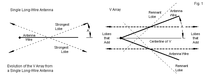
The V Beam (Vee-Beam) is just one half of a Rhombic.
I am using, two 1200 foot per leg V-Beams, to fill in a few directions where I could not add four poles as required for the rhombic. I don't see much real day to day difference form the rhombics, However these are very long Vs, even a 300 foot would provide good gain on the higher HF bands and work on 40 meters.
A great V beam 40 -10 meter setup would be two or three, 400 to 600 footers on a rotary switch, using just one tall support. A V beam is a good very low cost way to go, if you have a large lot. Which has the same gain as a 3 or 4 element mono-band beam, however providing that gain all those bands.
V-Beam Basics
The terminated V array forms a V-beam, that is, a directional terminated V array. The technique seems simple enough. We simply place a non-inductive terminating resistor at the end of each leg. However, the resistor cannot simply float at the terminating end of the wire. One option is to bring the terminated end of the leg wire to ground. Alternatively, we may run a wire between the two terminated wires end and place the non-inductive resistor at the center.
Add more V Beams on a tall support and run them out in multiple directions, they can even slope back towards the ground.
The above, is a switch box using 10 amp relays to switch the open wire feeders.
The terminated V array forms a V-beam, that is, a directional terminated V array. The technique seems simple enough. We simply place a non-inductive terminating resistor at the end of each leg. However, the resistor cannot simply float at the terminating end of the wire. One option is to bring the terminated end of the leg wire to ground. Alternatively, we may run a wire between the two terminated wires end and place the non-inductive resistor at the center.Fig. 6 shows 4 classic implementations of the terminated V-beam. Model A places the feed=point close to ground and slopes the legs upward to their normal (1 wavelength) height. (The opposite slope for the array is also possible. See model A1.) The terminated ends run vertically to the ground, with the terminating resistors at ground level. The model will use the same ground-rod technique used in constructing models of single terminated long-wire directional antennas. However, none of the models will use a vertical wire at the feed=point end. The single long-wire beams could use the vertical feed=point end with the actual feed-point close to ground. If we apply that same technique to the V-beam, we end up with the 2 legs in parallel, which does not yield much gain or directivity. The source-ends of the legs must have the feedline across them in a series connection to yield the correct addition of peak lobes from each leg.
Selecting the correct values of the 2 terminating resistors is not so simple as it was with the single long-wire beam. As the following trial table shows, the value is not exceptionally critical, although we may have reasons for choosing one value over another. For design purposes, the reasons may involve the best compromise among gain, front-to-back ratio, and impedance. In practical installations, the reasons generally focus on what non-inductive resistors may be available. The test table (and others to follow) uses NEC-4 models with 5 wavelength legs 1-wavelegnth above an average SN ground.
Terminating or not see below
So where to find large non-inductive resistors are used to terminate the antennas
W7YRV/SK used a 200 foot tower and spaced 9 sets (18 wires) of V beams, 360D around the tower. Then he used two sets each to form his "W7YRV X- Rhombic", such a great antenna that he used on 80 meters and up. When in QSO with him on 40 meters he would just start rotating it, and the S numbers at my QTH in KS, would change by one to two S units on each switch, running a 1000 mile day time path. 40 over 9 with a KW, to S2 or 3 in the noise. He gave me his switch control unit. I will write more on this system later, also see his blog which is still up. http://w7yrv.blogspot.com/2013/
Feed System info
See
TO SEE the complete Blog list check @ https://www.k0uo.com/k0uo


Good info