


Vertical Polarized Half (1/2) Rhombic Array
- skylarkcolo

- Oct 2, 2024
- 9 min read
Updated: 3 days ago

In the year 2021, the K0UO station undertook a significant enhancement to its communication capabilities by installing a vertical polarized Half (1/2) Rhombic antenna, specifically designed to operate across the 40 to 6 meter frequency bands. This particular antenna configuration is known for its efficiency and effectiveness in both transmitting and receiving signals, making it an excellent choice for amateur radio operators and professionals alike. With a center height of 160 feet, the antenna of 18 wavelengths on 40 meters and is strategically positioned to maximize its range and performance, allowing for clearer communication over long distances.
K0UO emphasizes the scientific method: model → build → far-field test → refine


Above the ground plane, the half-rhombic antenna exhibits the radiation patterns of a full-rhombic. antenna while the input impedance is half that of a full-rhombic antenna.
One of the crucial factors influencing the performance of this antenna is, that it is dependence on a high-quality earth ground. The resistance of the ground rod system plays a vital role in ensuring that the antenna functions optimally. A good plan would be to use radials for each ground, at the end and feed points, or a wire on the ground under the antenna, from end to end. In my installation, two 5400-foot deep oil-well casings has been utilized as the grounding mechanism. This choice is particularly significant because deep oil-well casings are made from large conductive pipe casing that provides an excellent grounding path, which is essential for minimizing the risk of electrical interference and enhancing signal clarity.


This grounding system serves a dual purpose; it not only provides an effective ground for the antenna's operation but also acts as a protective measure against lightning strikes, a common hazard in outdoor large wire antenna installations. The environmental conditions at the K0UO site further contribute to the antenna's performance. The area is characterized by its distinctive red soil, which is notably high in iron content. This particular soil composition is advantageous because iron-rich soils tend to exhibit superior electrical conductivity (EC). High EC is critical for ensuring that the ground system effectively dissipates electrical energy, which can improve the overall efficiency of the antenna. Additionally, the conductive properties of the soil can enhance the antenna's radiation pattern, allowing for better signal propagation and reception. In summary, the installation of the 40-6 meter vertical polarized 1/2 Rhombic antenna at K0UO not only showcases advanced engineering and design but also highlights the importance of environmental factors and grounding techniques in optimizing radio communication systems. The combination of a high center height, a robust grounding system using a deep oil-well casing, and the naturally conductive red soil creates an ideal scenario for effective amateur radio operations, ensuring that the K0UO station remains a reliable and efficient hub for communication.

"K0UO, Miles of WIRE, in the AIR, and ON the AIR daily"
The antenna array spans 18 wavelengths on the 40-meter band (2340 feet) and is positioned at a height of 160 feet. It is constructed from a triple galvanized wire rope cable with a diameter of 1/4 inch, meaning it is not merely steel, but triple coated with galvanization. The galvanized cable consists of zinc and other components with higher conductivity. Most commercial AM broadcast towers are zinc-plated. All the large wire antennas are tensioned (pulled tight) to withstand a pull of 1000 to 2500 lbs.

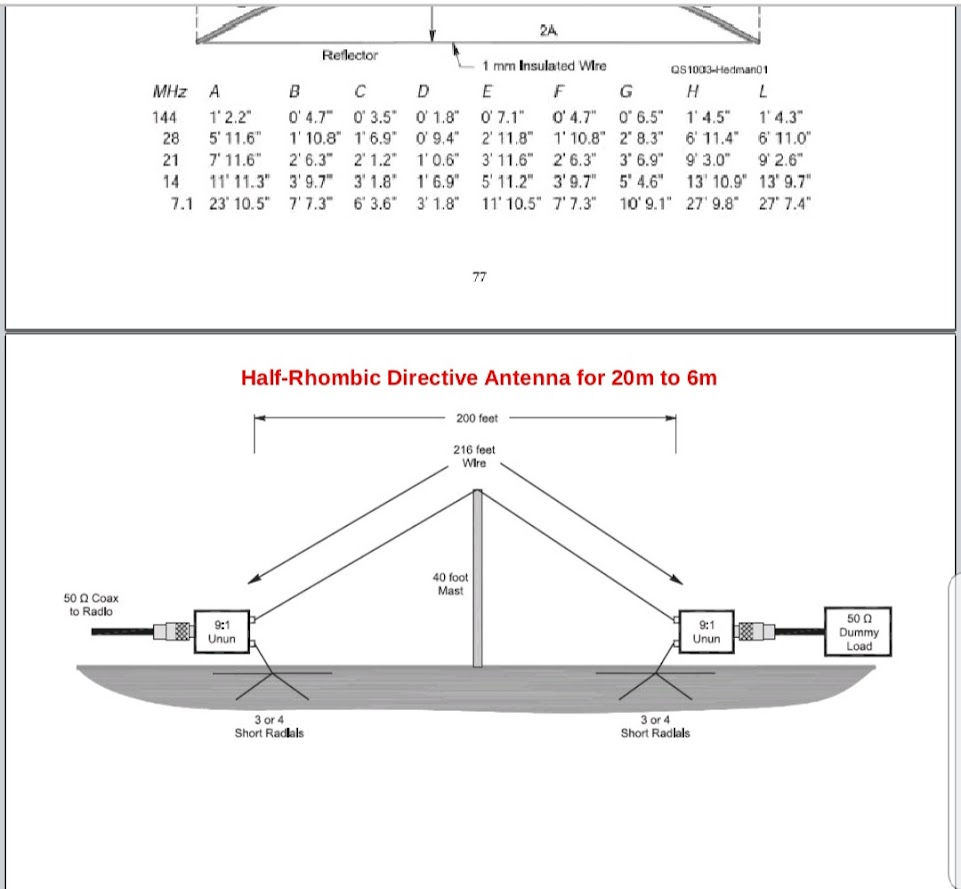
The vertically polarized 1/2 Rhombic antenna provides a wider beam than the full Rhombic antenna, with only as reduction in gain.
However, it requires only a single tall support. To enhance its gain, simply increase its length.
The directivity of the antenna is aligned with the plane of its legs. By feeding one end with a 9:1 balun and leaving the other end open, a bi-directional signal is achieved. Terminating the far end results in a unidirectional signal at the terminating end. This high-gain antenna is utilized where a low angle of radiation is required.
This antenna also exhibits some higher angle radiation, which can be advantageous for amateur use, allowing communication with nearby stations.
When assessing the design and application of the vertically polarized 1/2 Rhombic antenna, it is essential to understand its unique characteristics and how they can be leveraged to meet specific communication needs. The 1/2 Rhombic antenna is particularly noted for providing a wider beam-width compared to the full Rhombic configuration. This increased beam-width enables broader coverage, making it advantageous in situations where signals need to be transmitted or received over a larger area.
It is important to acknowledge that this results in a trade-off with gain; the full Rhombic antenna typically offers higher gain due to its more concentrated radiation pattern. However, the 1/2 Rhombic design is inherently simpler, requiring only one tall support structure, which can significantly reduce installation complexity and costs.
To enhance the performance of the 1/2 Rhombic antenna, a simple approach is to extend its length. Lengthening the antenna results in higher gain, which is particularly beneficial for long-distance communications. The gain properties can be adjusted to suit the user's needs, offering adaptability in various operational situations. The antenna's directivity is aligned with the plane of the legs, maximizing signal strength in that direction. When the antenna is fed at one end with a 9:1 balun, it enables the generation of a bi-directional signal, thereby supporting efficient communication in both directions along the antenna's axis. This capability is especially advantageous for point-to-point communications, where it is essential to transmit and receive signals without the need to adjust the antenna's position.
When the far end of the antenna is terminated, it transforms the setup into a unidirectional antenna. This configuration is ideal for users aiming to concentrate the signal in a specific direction, effectively eliminating unwanted reflections or interference from the opposite side. This high-gain antenna is crucial in scenarios where a low angle of radiation is essential, such as in long-range communications where signals must penetrate the ionosphere to reach distant stations. The low angle of radiation ensures superior propagation characteristics, vital for effective communication over vast distances.
Moreover, the 1/2 Rhombic antenna demonstrates some higher angle radiation, providing significant advantages for amateur radio operators. This feature enables operators to establish reliable communication with nearby stations, facilitating local contacts and enhancing overall communication capabilities. The ability to effectively communicate with both distant and nearby stations makes the 1/2 Rhombic antenna a versatile choice for amateur radio enthusiasts.
By comprehending the various configurations and optimizing the antenna's length and feed methods, users can customize their setup to enhance performance according to their specific communication needs.

The half-rhombic antenna is essentially one side of a rhombic antenna placed against the ground. Its performance is limited by the lossy nature of the soil, which affects its ability to function as a true rhombic antenna due to ground reflections and losses. Despite its designation, this antenna operates more like a terminated, end-fed, inverted V, with optimal performance when the center point is slightly elevated above the ground. In Bruce's 1931 article, it is referred to as an inverted-V, while the term "half-rhombic" was later coined by other practitioners. Various adaptations of the rhombic antenna have been developed to fulfill specific commercial, governmental, and Department of Defense communication needs, resulting in highly intricate wire structures that extend beyond the scope of these introductory notes. Nonetheless, the variations presented here should provide a solid foundation for understanding the classical literature on advanced rhombic designs.
The Rhombic and V-Beam antenna array remains an outstanding HF antenna for commercial applications, maritime shore stations, military operations, broadcasting, frequency-agile requirements, high-speed trading, diplomatic communications, EME, and amateur ham radio stations.


All long Traveling Wave Antennas are renowned for their remarkable capabilities in significantly reducing QSB (Quasi-Static Fading) during both transmission and reception processes. This unique characteristic makes them an invaluable asset in the field of radio communications, where maintaining a consistent and clear signal is crucial for effective communication.
Understanding QSB Fading
QSB fading refers to the rapid fluctuations in signal strength that can occur due to various atmospheric conditions, terrain variations, and other environmental factors. These fluctuations can lead to interruptions in communication, making it challenging for operators to maintain a stable connection. Long Traveling Wave Antennas, by their design, mitigate these issues effectively.
Design and Functionality of Long Traveling Wave Antennas
The design of long Traveling Wave Antennas allows them to operate over a wide range of frequencies. This versatility is essential in combating QSB fading, as it enables the antenna to adapt to changing signal conditions and maintain a steady performance. The principle behind these antennas involves the propagation of waves along the length of the antenna, which helps in distributing the signal more evenly and reducing the impact of fading.
Advantages of Long Traveling Wave Antennas
One of the key advantages of using long Traveling Wave Antennas is their ability to provide a more uniform radiation pattern. This uniformity plays a significant role in minimizing the effects of multipath propagation, a common cause of QSB fading. By ensuring that the signal is transmitted and received with consistency, these antennas enhance the overall reliability of communication systems. Additionally, long Traveling Wave Antennas often feature a higher gain compared to traditional antennas. This increased gain contributes to a stronger signal, which is particularly beneficial in challenging environments where obstacles may otherwise weaken the transmission. As a result, users experience fewer interruptions and improved clarity, whether they are transmitting or receiving signals.
Applications in Various Fields
The advantages of long Traveling Wave Antennas extend across various fields, including amateur radio, commercial broadcasting, and military communications. In amateur radio, operators benefit from the reduced QSB fading, which allows for clearer conversations over long distances. In commercial broadcasting, the reliability of signal transmission is paramount, and these antennas help ensure that listeners receive high-quality audio without significant interruptions. In military applications, where secure and reliable communication is critical, long Traveling Wave Antennas provide the resilience needed to maintain communication links, even in adverse conditions. Their ability to function effectively in diverse environments makes them a preferred choice for tactical operations.
Conclusion
In summary, long Traveling Wave Antennas are exceptional tools in the realm of radio communications, particularly due to their outstanding performance in minimizing QSB fading. Their design, functionality, and adaptability contribute to a more reliable communication experience for both transmitting and receiving signals. As technology continues to advance, the importance of such antennas in maintaining effective communication cannot be overstated, making them an essential component in various applications across multiple fields.
It is like Diversity, theses large arrays cover a lot of area. My station uses over a mile of wire, so you are both listening and transmitting signals coming and going at different angles. Signal-to-noise ratio (S+N/N ratio, or SNR) is one technical aspect not too many amateurs give a second thought about, however if you can't hear them you can't work them. This is very apparent on audio reception, long Traveling wave antennas eliminates much of the audio amplitude fading for both transmit or receive. The RF signal is almost never in a stable phase relationship at both places at the same time. This means the signal will have random phase and amplitude differences. The arrival angle and polarization of incoming signals will change. This generally results in the fading, by having many wavelengths of wire in the air, the chances are that while one experiences a fade, the other will not. The power is in the diversity size of the array and what you can now hear with out QSB fading. Traveling wave antennas are just quieter and have substantial noise reduction. That is why so many people use the Beverage receive antennas.


"I hope others will carry on the tradition, and art of building the large Rhombic Arrays in the future". It is truly the "PHD" of wire antennas.
The K0UO antenna test range site utilizes the 4KS Walz airport and its surrounding area as an effective learning environment for STEM (Scientific, Technical, Engineering, & Mathematics) antenna projects in a real-world outdoor setting. If your group is involved in a university aerospace or antenna research STEM program, please reach out. The KØUO Rhombic Antenna Farm and Antenna Test Range: Proudly home to the World's Largest amateur radio (ham), High Frequency (HF) Wire Arrays, with miles of wire actively in use daily.

Historic Preservation: The K0UO station diligently preserves and uses components and insulators from renowned, historic radio arrays, including those from W6AM (Don Wallace), W7YRV Roy, BBC, Voice of America (VOA), and many others.
"The K0UO station is unlike any other ham station globally," making it truly unique as a Big Gun Mega Station. It is one of the few capable of constructing and utilizing very large Rhombic and V Beams, along with a variety of other antennas and AI. K0UO features the largest operational HF wire antenna in the world.


TO SEE the complete Blog list check @ https://www.k0uo.com/k0uo
TIP: It is a Blog, so just SKIP the Blogs HEADER and go right down to the blog.


These really work and are very easy