


Log-Periodic Dipole Array or LPDA
- skylarkcolo

- Jun 18, 2024
- 15 min read
Updated: Jul 5

The main advantage of an LPDA over other beam antennas, is its wide frequency coverage, which allows it to operate efficiently across multiple bands without the need for tuning, and no moving parts or traps to fail.
Antennas.....before Amplification

The LPDA is a purposefully designed antenna, not a compromised one, which was part of a United States Air Force "Secret" project in the early 1950s. It provides more gain than Hex-beams and most Triband Yagi beams. Then in 1957, R.H. DuHamel and D.E. Isbell of the University of Illinois published the first work on what was to become known as the log periodic dipole array.
The impedance of the Log-periodic antenna is a logarithmically periodic function of frequency. The main advantage of an LPDA is its consistent characteristics over a wide frequency range, offering very broad bandwidths without moving parts, fiberglass, traps, or wires that can break, and it is directional. It delivers more gain than a Hexbeam or a small Tri-band Yagi. This is why many services and agencies rely on LPDA antennas for maintaining reliable long-distance communication links for embassies, energy companies, high-frequency stock trading groups, the FBI, FAA, ship-to-shore communications, MARS, emergency operations centers, FEMA, and armed forces worldwide. The Log can handle very high RF power, and many commercial short-wave broadcast radio stations use Logs with up to 500,000 watts. A Log is an excellent replacement for the no longer produced SteppIR antenna.
This statement sums it up
MONO-BANDERS v. LOG-PERIODICS! – ONE BAND v. MANY BANDS!

Understanding the Log-Periodic Antenna Design
The Log-periodic antenna is a fascinating and sophisticated design that employs half-wave dipoles for its construction. In this configuration, every element of the antenna is actively driven, meaning that each dipole contributes to the overall performance of the antenna, rather than relying on a single active element as in some other antenna designs. The elements of the Log-periodic antenna are arranged in decreasing lengths along the boom, which is the horizontal support structure of the antenna. This variation in element lengths is crucial, as it allows the antenna to effectively cover a wide range of frequencies.


Broadband Capabilities and Functionality
The electrical functionality of a Log-periodic antenna is that of an active frequency agility broadband array. This means that it is capable of operating efficiently over a wide spectrum of frequencies, simulating the performance characteristics of a series of full-sized three-element Yagi antennas. The Yagi antenna is known for its directional properties and gain, and while the Log-periodic antenna shares some visual similarities with the Yagi design, its operational principles and capabilities differ significantly.

MONO-BANDERS v. LOG-PERIODICS! – ONE BAND v. MANY BANDS!
Operational Mechanism
The Log-periodic design operates in a manner that is quite similar to that of a three-element Yagi antenna. However, what sets it apart is the way in which the dipole elements are fed. In a Log-periodic antenna, the elements are connected through a common transmission line, allowing for alternate feeding of the dipoles. This connection is vital as it enables the antenna to shift its active region in response to changes in frequency. As the frequency increases, the active region of the antenna shifts forward along the array, moving towards the shorter elements. This dynamic adjustment ensures that the antenna remains efficient across its operational bandwidth. Some LPDAs use cold boom others use Hot booms which we will discuss late in this blog. LPDA elements is virtually 100% efficient, it also closely matches the 377 ohms impedance of free space, a further contribution to its efficiency.

Frequency Response and Active Regions
One of the most intriguing aspects of the Log-periodic antenna is its ability to handle changes in operational frequency. As the frequency shifts upward, the active region of the antenna does not remain static; instead, it migrates among the various elements. This means that not all elements are active at any given moment, allowing the antenna to maintain performance across different frequencies. The design cleverly utilizes the principle of having some elements act as passive radiators, which play a crucial role in enhancing the overall signal reception and transmission capabilities of the antenna.
A little known fact is that a HF LPDA 30 -10 actually works on 6 meters, but the pattern is not straight off the front, the main lobe on 6 meters in split and has two smaller lobes about 45 degrees each off the front with about the same gain as the main beam was on 10 meters. but Mike Staal (K6MYC) of M2 and Mark Chouinard (K5YAC) at Tennadyne, have told me that they know it, but don't advertise it, because the lobe is not direct off the front, it is just too confusing. I have used this to my advantage for years. Being in Kansas I can work stations in both the NE and SE, or NW and SW at the some time, and not move the Array.
See later down this blog for more info on adding 6 meters to a log call a Log-Yag, .

Structural Similarities and Differences with Yagi Antennas
Although the Log-periodic antenna (yagi-style log periodic) might look similar to a Yagi antenna due to its linear element arrangement and boom, their electrical properties and operational mechanics are fundamentally distinct. The Log-periodic design includes both active and passive elements, enabling a more intricate signal interaction that can enhance performance across various applications. The passive elements help direct and reflect signals towards the active elements, thereby boosting the antenna system's overall gain and efficiency. In essence, the Log-periodic antenna is a versatile and efficient broadband design, using half-wave dipoles of different lengths to cover a wide frequency range. Its unique feeding mechanism and ability to dynamically shift the active region make it a powerful tool for diverse communication needs, setting it apart from traditional designs like the Yagi.
A complex impedance matching setup is unnecessary for driving an LPDA, with most using a 300-ohm balanced or 50-ohm unbalanced feed system.
With a gain of +6 dB and when installed at half a wavelength above the ground, it achieves 6 dB more ground gain, about 2 dB more than a Hex-Beam, with significantly more front-to-back ratio.
The T-6 is approximately the same weight as a Hex, but it is much stronger and far easier to assemble. Operating over bandwidths ranging from 2:1 to 4:1 is typical, with a nominal half-power beam width of 65 degrees. In ice or hail storms, the Hex-beam's wires can break, and UV exposure from the sun on the ropes and fiberglass leads to damage and splintering. A 10:1 bandwidth is achievable in VHF/UHF designs and for TV reception. This wide bandwidth offers a significant advantage over a Yagi and other antenna types, without the need for traps, wires, or moving parts that might fail.
Not only does the typical Ham Log LPDA work 20-17-15-12-10m (and some like the T11 do more than that) but they cover the frequencies in between, so also for MARS work
Again this statement sums it up
"MONO-BANDERS v. LOG-PERIODICS! – ONE BAND v. MANY BANDS!"


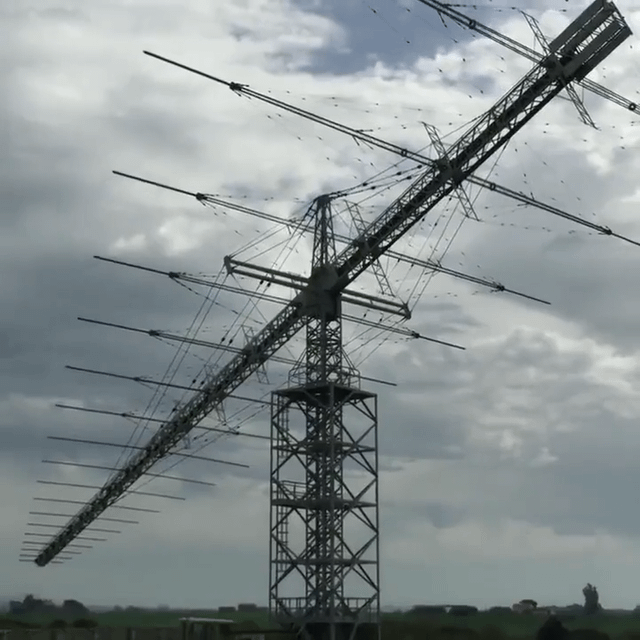
Below the Tennadyne in use at K0UO
Unlike many LPDA antennas, the Tennadyne has minimal wind resistance. I've had one installed on a 195 ft tower for 20 years without any maintenance, enduring ice, hail, and numerous 80 mph wind storms.
Mark K5YAC at Tennadyne produces an outstanding antenna.
Visit the Tennadyne website https://www.tennadyne.com/
More info about Tennadyne history and owner
BELOW: I am using two Tennadyne Logs, one at 100 feet, installed in 2023. The other at 195 feet was installed in 2006

The Tennadyne Log-Periodic Dipole Arrays (LPDA) are robust and comparable in price and size to a Hex. However, they offer twice the gain and improved front-to-back ratio, with minimal risk of storm damage. They feature no traps, lossy coils, wires that could break, or moving parts. Once assembled, the SWR remains low without needing any tuning, and you can extend the mast through the array to mount another antenna, such as a VHF/UHF antenna, on top, which you can't do on a Hex beam.

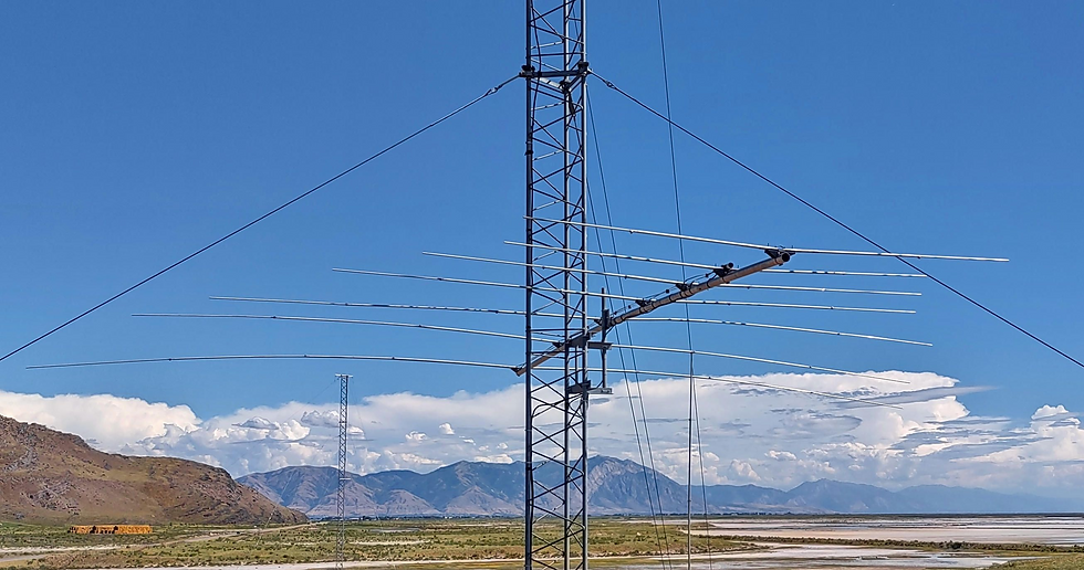
Above: Is at K8CU, an LPDA stack, at one time I also had a stack, using two T12 Tennadynes on a195 foot Rohn rotating tower, making a very high gain system
Tennadyne LPDAs use a double boom, one above the other, that perform a double duty. They act as (1) a constant impedance transformer, providing a constant impedance match between the very high impedance of the LPDA elements and your 50-52 ohm feedline. They also (2) provide a rigid fore-to-aft structure much like a truss, giving very strong mechanical support to the antenna elements. Overall, this boom structure is exceptionally strong! Each boom is precision machined so that the elements pass directly through, maintaining constant impedance through out the bands.
Note:
My Hex beams did not hold up long with the wind, ice and UV from the sun, but the T-6 is lightweight and much like a TV antenna. The T-6 assembly is not as challenging as a Hexbeam, where balancing wires and spreader ropes tension that makes the Hex structural strong requires careful handling. Tangling of the Hex wire elements can be stressful at best. The T-6 and T-8 are not much difference in cost, compared to the Hexbeam which has only half the gain.
For a great performing, low cost, strong long lasting beam, the T-6 or T8 is the way to got

Coax should be choked, in order to decouple from the boom.
Tennadyne uses a hot boom, where the two booms run parallel over the length of the antenna. The booms are insulated, from the mast and tower.
So more on the Tennadynes, where it uses a hot boom setup, the coax shield will radiate and also sent RF voltage away from the antenna. Previously, I did not tape the coax to the boom, but just let it hang 6" below, to decouple it from the boom.

MONO-BANDERS v. LOG-PERIODICS! – ONE BAND v. MANY BANDS!
In the past for my receive only LPDAs hot-boom feed systems like a T6-T12, I have run the coax through the center of the boom, and added a feed-through hole at a zero voltage point on the boom. This eliminates the need for any balun.
Note, this K0UO blog uses dB gain, not dBi when providing antenna gain data, don't be fooled by dBi.
After testing the hot booms on the antenna range and pulling my hair out about all of this stuff.
Now I just tape it to the boom, like the instructions say,
but I use a choke on the coax, where it exits the boom at the rotor loop to the mast, for an isolator of common mode (I like the snap on sleeve chokes that Palomar sells, use 5 or more 31s) easy, and it solves and problems. Using a common mode isolation device, the SWR is also stable and lower with the CMC gone. NOTE: You will still want to use the COLLINS Balun at the end of the LPDA boom. https://palomar-engineers.com/antenna-products/1-1-balun-kits/super-choker/Snap-On-Sleeve-Chokes-c21444185

So the CMC/RFI is eliminated and the array pattern is improved with more forward gain. Now all you need is to get on the air and start making QSOs!


Below: My antenna in Belize at V31KW, which has been installed for over 35 years, utilizing a Collins Log-periodic 237B-3 RLP/ LPH-1B (LP1002-5/30) setup for 5-30 MHz use, positioned at 90ft. It has withstood several hurricanes over the years. Although a large LPDA, this Log offers no more gain than a Tennadynes on 20 - 10 meters, http://www.collinsradio.org/wp-content/uploads/2022/12/Q3-2018.pdf
Now sold by https://www.usantennaproducts.com/antennas/models-lp-1005-lp-1001-lp-1002/ or https://www.antennas.com/product/lph-1b/


Logarithmic Periodic Dipole Antenna Calculator
The ratio of the successive element lengths (L_(n+1)/L_n) be equal to some constant k, and that the distance between elements (d_(n+1)/d_n) also equal k.

Also See:
One method which will provide up to 10.5 dB gain is to decrease the apex angle, a, and increase the periodic function, τ. An angle of 45 degrees with a τ of 0.707 and a separation angle of 45 degrees will give us 7.7 dB gain with little change in azimuth pattern and an acceptable decrease of vertical coverage to 66 degrees. The length from apex to rear element grows from about 30 feet to about 42 feet (Table II) and the total number of elements increases slightly. Changing the apex angle to 15 degrees will permit 10.5 db. gain, but the antenna will become much longer and the number of elements will be considerably greater.


TEL-143042-135 is 14 through 30 MHz, featuring 16 elements on a 42 ft. long, 3 in. diameter extra-heavy duty boom 135 mph wind rating, SEE at https://www.dxengineering.com/parts/tel-143042-135


Visualizing the "Virtual Traveling Wave"
One of the most fascinating concepts of a LPDA that needs explained, is how an LPDA behaves like a living, shifting entity.
The Dynamic Active Region: Unlike a Yagi where every element is dedicated to one band, an LPDA utilizes a shifting "Active Region". At any given frequency, only about 2 to 3 elements are actively resonant.
The Wave Travel: When RF energy is fed into the front of the boom, it travels along the transmission line. The forward elements are too short and act merely as a capacitive load, ignoring the energy. When the energy reaches the elements that are roughly a half-wavelength long, it violently couples to them and radiates into space.
The "Black Hole" Effect: Any remaining energy that passes the active region hits the longer elements behind it, which act as a reflector. Virtually zero RF energy ever reaches the longest, outermost element when operating at the high end of the band.


Below: A YouTube of the repair & refurbishing of the LP-1002 Log Periodic Beam Antenna @ the Northern Utah WebSDR 4

A large logarithmic antenna protel radio link ARL531 5-30 MHz being installed


Adding 6 meters, it is possible to add a passive (parasitic) director to a 20–10 meter LPDA (typically covering ~14–30 MHz) to provide useful directional gain and performance on 6 meters (~50–54 MHz), though it won't fully integrate 6m into the LPDA's broadband log-periodic behavior like the HF bands.
Why This Works
LPDAs have their shortest elements at the front (high-frequency end). A parasitic director—shorter than the shortest driven element and placed ahead on the boom—can act as a Yagi-style director for higher frequencies, like 6 meters.
This improves gain, directivity, and front-to-back ratio on 6m (or near it) via parasitic coupling, with minimal detuning of the lower HF bands if positioned and tuned properly.
Antenna experts (e.g., L.B. Cebik and others) describe this as a common hybrid "Log-Yagi" modification: adding one or more parasitic directors to boost performance at the upper frequency extreme or beyond the designed range.8da08d41f4857c2f24
Design Considerations
Element Length — Tune the director for ~50–52 MHz (slightly shorter than a 6m half-wave dipole, e.g., ~8.8–9.2 ft total, depending on diameter and spacing—typically 4–5% shorter for director role).
Position — Place it 0.1–0.15λ ahead of the shortest LPDA element (at 50 MHz, that's ~6–9 inches, scaled up for practical boom; often 0.1–0.2λ for HF hybrids).
Effects — Expect 2–5 dB added gain on 6m, better pattern, but SWR/match on 6m will depend on the existing feed—may need a separate match or accept higher SWR. HF bands usually remain largely unaffected.

Below: A large Log using the old Collins 237B-3 RLP design, now LPH 1C or US Products LP-1005AA


InnovAntennas 13 Element HF Log Periodic Dipole Arrays provide super wide-band, high performance from 10 to 54 MHz. InnovAntennas LPDA's are designed using the very latest computer optimization techniques such as Dense Element Log Periodic Dipole Array (DELPA). This type of antenna was designed with specifications for a broadcasting center. The DELPA-13 has 13 elements placed above the 37.73 ft. (11.5 m) by 3 in. (76 mm) square boom, from which all elements are insulated. The feed point is 200 Ohm and includes a 20 kW 4:1 balun. Feed-line between the elements is silver plated hard-drawn copper wire spaced to produce a 300 Ohm balanced-line feed.

K0UO near Kiowa, KS has High-Performance Antennas: Using large High Frequency HF stacked LPDA-Yagi beams, Rhombics, V Beams, Curtain arrays, Four-square phased verticals on specific bands, optimized for low noise and very efficient and high gain

Cushcraft and Hy-Gain Manufacturing now bought by ITU Corporation in 2026
I hope they bring back some Logs, LPDA Log-periodic antenna. the Hy-Gain one was a nice antenna, and used by commercial and DOD. Like the LP-1010A/ LP-1010AN I, LP-1009A 20 to 10 meters, Telex (Not Telrex) made it. Telex made good antennas built like battleships, in Lincoln NB. They owned Hy-Gain before MFJ.

Remember the main advantage of an LPDA is its consistent characteristics over a wide frequency range, offering very broad bandwidths without moving parts, fiberglass, traps, or wires that can break, and it is directional. It delivers more gain than a Hexbeam or a small Tri-band Yagi.
The Best Antenna is one that is "In the Air and On the Air"! As any good antenna experimenter knows, the more antennas the better, that way you can test and see how they are really working. You won't know you have a good antenna if you can't compare it with others!
Calculator to build a LPDA
LPDA Links
COMPARISON OF COLLINS LOG -PERIODIC ANTENNA AND
MILITARY RHOMBIC ANTENNAS, SEE PAGE 79 UP https://w1op.com/237/Collins%20Antennas/Collins%20Antennas%201960.pdf
"MONO-BANDERS v. LOG-PERIODICS! – ONE BAND v. MANY BANDS!"
Install of a large Log
The K0UO antenna test range site utilizes the 4KS Walz airport known as "Antenna University", and its surrounding area as a practical learning environment for Scientific, Technical, Engineering, & Mathematics (STEM) antenna projects in an outdoor real-world setting. If your group has a University aerospace or antenna research STEM program, let me know. We are using AI which is now becoming an advanced tool in analyzing, developing, and expanding research in RF and antennas.

TO SEE the complete K0UO antenna Blog list check @ https://www.k0uo.com/k0uo
TIP: It is a Blog, so just SKIP the Blogs HEADER and go down to the blog.


I just installed a T6 at 38ft, and it blows away the old hex-beam, I was happy with the hex, but then I saw and heard a 2 to 3 S unit increase. You don't know what you don't know, until you have something to compare it too.
I had a large ice storm last week, like the one that killed the hex last year, the T6 was heavy loaded and bounced right back, thank you for the info.
Real F/B and it had the gain.
ALSO, I installed a VHF/UHF on top with a pipe, you can't do that with a hex.
The information on logs LPDA is very clear and direct. You've had extensive experience and you're using them at probably the world's largest antenna range of 1200 Acres. There's rhombus or something else when I heard you on the air the other day running only 100 Watts you were 30 over 9 on the East Coast on 40 m midday. 73
I wished I had known about a Log before, I rebuilt the last three hex beams; that have been destroyed by ice and wind.
I got a T6, and it has more gain and F/B and same size as the Hex.
A Hex work but even a small T6 LPDA has a noticeable more Gain and F to B at low cost.