


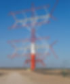
The stacked K0UO curtain Rhombic array @ 195 foot. Using a 600 ohm current feed system
- skylarkcolo
- Mar 2, 2022
- 9 min read
Updated: 1 day ago

The antenna uses a distributed curtain type fed arrangement. It utilizes a reflector instead of terminating resistors for direction providing maximum front to back, and not wasting power in the terminating resistors. Up to 3db is added to the antenna forward gain and another 3db by not utilizing resistors, while also increasing the front the back ratio is even higher (it is like a brick wall). This antenna is steerable, plus or minus 30° using electronic phasing. The upper X-Rhombic is at 195 feet, the lower X-Rhombic is at 100 feet. This antenna is designed with steerable directivity and wave angle phasing. The main area of interest for this antenna is Northern to Southern Europe, the Mediterranean, Northern Africa and the Mideast.
Antennas.....before Amplification
Historical High-Power DX Arrays
Although not always labeled exactly “Billboard,” many classic HF rhombic and curtain arrays used in the mid-20th century for point-to-point and broadcast services employed stacked elements and reflectors to achieve high gain and directivity. Some early broadcasting authorities even experimented with stacked/interlaced rhombic arrays as alternatives to pure curtain designs with over 20dB of gain.

It is now "In the Air and On the Air" 20 db forward gain
What is HRS/USIA Array, Distributed Fed Curtain using Stacked X Rhombics Steerable (DRS)?
Most people incorrectly call the HRS, USIA or Distribution fed curtains, "Sterba curtains". But there are some big differences in performance and construction of broadcast type curtain arrays, like the horizontally polarized Distributed Fed Curtain arrays, or USIA arrays, and the much lower gain vertically polarized Sterba curtain or Bobtail antenna.
Distributed fed curtains use a series of common points, each feed from equal length low loss transmission lines, to distribute power. Curtain" refers to the planar reflector behind the driven elements (Billboard). The conductor loss is less, phase error is significantly reduced, and all elements receive equal currents. This feed method places conductor resistances in parallel, and makes array patterns stable over very wide frequency excursions. In addition to having more gain, a distributed fed curtain (such as USIA arrays used at Shortwave broadcast sites) can be used over a 2:1 or broader frequency range with minimal gain and pattern change. It is very easy to make a distributed feed curtain operate on 40 & 20 meters with full gain and no pattern distortion. A distributed or branched feed curtain also allows designers to use optimum element spacing. This means a 4-element branch fed curtain can provide the highest gain per acre of any antenna design. The stacking height compresses the signal in elevation. This is the vertical count of layers, the number of columns, bays, or array width compresses the signal in azimuth. Despite occupying a tiny fraction of the space required for the VOA type rhombics, the USIA style curtains are the highest gain arrays used at VOA's International and others Broadcasts, like the new WBCQ Ampegon 23db gain antenna system. However this type of antenna is not commonly known to most amateur operators, where the associated feeder system in a multiband, horizontal-dipole, curtain antenna, as used for high power operation in short-wave broadcasting. These forms include vertically polarized arrays like the Bobtail, Sterba, Bruce arrays, that only have 25% the gain of a standard distributed feed array, like a USIA. They also more commonly include horizontally polarized arrays like bedspring arrays, H curtains, lazy-H antenna arrays, or distributed feed curtains like the USIA arrays, or HRS arrays used for shortwave Broadcast. The nomenclature conventionally used to describe horizontal-dipole, curtain antennas has been standardized internationally, using the form HR m/n/h, with the following meaning (International Telecommunication Union, 1984):
HR: | horizontal dipole curtain antenna with reflector curtain |
m/: | number of dipole elements in each row |
n/: | number of dipole elements in each stack (one above the other) |
h/: | height above ground, in wavelengths, of the bottom row of radiating elements |

The top "X" Rhombic antenna is at 195 Feet just under the HF Log-beam, the lower element is at 100 foot, A Stacked Curtain Rhombic HRS “Billboard” Array with 20dB of gain:
A very large, stacked, directional shortwave antenna made of wire elements arranged like a curtain, backed by a reflector screen, designed to beam high-power HF radio signals toward a specific part of the world. This is demonstrating how stacked rhombic and curtain feed techniques can be combined and are at K0UO
"K0UO, Miles of WIRE, in the AIR, and ON the AIR daily"

The K0UO Distributed-fed Curtain (Billboard) uses stacked X Rhombics, and it is a steerable design. To see more info on the W7YRV "X" Rhombic design, see Roy's Blog @ w7yrv.blogspot.com/2013/
An HRS type antenna is basically a rectangular array of conventional dipole antennas strung between supporting towers. In the simplest case, each dipole separated from the next by 1⁄2 λ vertically, and the centers of each dipole are spaced 1 λ apart horizontally. Again, in the simplest case (for a broadside beam), all dipoles are driven in phase with each other and with equal power. Radiation is concentrated broadside to the curtain. The HRS type antenna is an example of a curtain array antenna. It has horizontal dipoles, series dipoles, lazy H, or in this case a X Rhombic with a Reflector behind them, and the RF beam from the antenna is Steerable. These antennas are also known as "HRS" with the ability to both steer and elevate or Direction/Azimuth. This is achieved electronically by adjustment of the electrical wave phases of the signals fed to the columns of antenna elements.
The drivers are radiating in horizontal, because horizontally polarized waves are less absorbed by earth reflections. The lowest row is mounted more than .75 wavelength above the ground, to prevent ground reflections from interfering with the radiation pattern. This allows most of the radiation to be concentrated in a narrow main lobe aimed a few degrees above the horizon, which is ideal for skywave transmission. A curtain array without a reflector has gain of 16 to 20 dB greater than a simple dipole antenna, now that is real gain!

A reflector can be added behind the array driver, typically about 1/8 to 1⁄3 λ away. The reflector consisting of parallel wires in the same orientation as the driver. If this was not present, the curtain would radiate equally forward and backward. The driven elements can be half-wave dipoles in phase, but K0UO is using a X Rhombic configuration mounted in a plane with the reflector wires oriented parallel or X to the driver.
In a simulation the HRS antenna radiation pattern consists of a main lobe with two major side-lobes.
K0UO's Curtain Array with Distributed-fed and using W7YRV, "X" Rhombic design, is a traveling wave antenna, which is a non resonant traveling wane antenna. The Rhombic antenna can radiate at elevation angles close to the horizon, and is called a Traveling wave or a Leaky-Wave Antenna (Rhombics are fast wave), with a phase velocity greater than the speed of light. This type of RF wave radiates continuously along its length, and hence the propagation wave=number kZ is complex, consisting of both a phase and an attenuation constant. A highly directive beams at an arbitrary specified angle can be achieved with this type of antenna, with a low side-lobe level. The phase constant of the wave controls the beam angle (and this can be varied changing the frequency, while the attenuation constant α controls the beam-width. The aperture distribution can also be easily tapered to control the sidelobe level or beam shape. Leaky-wave antennas can be divided into two important categories, uniform and periodic, depending on the type of guiding wire cable structure.
Don't underestimate the performance of the Rhombic, unless you have personally built and used one. Because of their excessive size (area) covering many acres, you see their real advantage of thousands of feet of wire in the air, which creates receive signal diversity, by capturing signals at different times and different angles, vastly eliminating fading QSB, and firing out the transmitted RF in the same way. Traveling wave antennas are very unique and unlike many other antenna in common use.
With the four rhombic arrays and three V-beams, the K0UO antennas effectively cover 14 directions, every 25°, the beam width of each array. The K0UO Curtain Array overlaps the NE arrays with even more gain, and can be phased with the NE rhombic.
STEERING
The phasing of elements employed in the K0UO stack are selected to form the required azimuth and elevation radiation characteristics required to work a station, (as an example, on 40 meters: low angle DX using the F layer or high angle for local stations with high D layer adsorption in the daytime).

Switching, which is quite complicated, is introduced in the feeders at ground level to slew the beam azimuthally or to change the radiation characteristics in the elevation plane by modifying the phase relationships between the various feed points. Since switching feeder line lengths in the switch-box provides control of the phase of feed to each array element, these arrays may be thought of as “phased” or “scanned.”
A design perimeter was the distance to the station desired, and how does the elevation angle required vary with time of day and sunspots (ionosphere reflection layer varies). Just think about the 40 meter amateur band going from F layer at night to an absorbent D layer in the daytime.

The K0UO “Stacked Curtain Rhombic HRS Billboard Array” are a specialized or hybrid description used in certain RF engineering circles, the general antenna family — HRS curtain arrays and stacked high-gain HF arrays — are in active service at major international shortwave broadcast sites (e.g., VOA, BBC, Deutsche Welle, RNZI) and in experimental amateur installations like the K0UO Rhombic Antenna Farm in Kansas.

A design perimeter should be the distance to the station desired, and how does the elevation angle required vary with time of day and sunspots (ionosphere reflection layer varies). Just think about the 40 meter amateur band going from F layer at night to an absorbent D layer in the daytime.
What is HRS/USIA Array, Distributed Fed Curtain using Stacked X Rhombic, Steerable (DRS)? It is the highest gain HF wire array system.
Below, WBCQ Ampegon 23db gain rotatable antenna in Maine USA

What is HRS/USIA Array a Sterba or Bobtail Curtain?
Most people incorrectly call the HRS, USIA or Distribution fed curtains, a Sterba or Bobtail Curtain. They are not the same. A Sterba does not even have 25% of the gain of a standard HRS.
There are significant differences in performance and construction between broadcast curtain arrays, like horizontally polarized Distributed Fed Curtain arrays or USIA arrays, and lower gain antennas like the Sterba curtain or Bobtail antenna used by some hams. A common misconception among RF engineers is calling a modern HRS (Horizontal Dipole with Reflector and Slewing) or Distributed-Feed VOA Curtain a "Sterba Curtain," which is incorrect. Although both are large, wire-rigged broadside arrays that hang vertically like curtains, their electrical architecture, physics, and feeding mechanisms are entirely different.
The Takeaway: Calling a VOA-type HRS curtain a "Sterba" is like calling a modern active electronically scanned array (AESA) radar a "rotary radar dish" just because they both scan the sky. Ernest Sterba did also invented a brilliant series-phased loop; the VOA/HRS arrays perfected parallel-phased, wideband distributed networks.
ALSO SEE
Building 16 rhombic arrays 1939
SEE K0UO's OTHER CURTAIN PAGE https://www.k0uo.com/post/current-distributed-feed-system-as-used-on-sterba-curtains-will-be-utilized-on-the-new-antenna
The K0UO antenna test range site makes use of the 4KS Walz airport and its surrounding area as a practical learning environment for STEM (Scientific, Technical, Engineering, & Mathematics) antenna projects in a real-world outdoor setting. If your group has a university aerospace or antenna research STEM program, please let me know.
The KØUO Rhombic Antenna Farm and Antenna Test Range: Home to the World's Largest amateur radio (ham), High Frequency (HF) Wire Arrays, miles of wire in the air and on the air daily. K0UO is also using AI, making it one of the largest and most sophisticated amateur radio stations in the world.
"I hope others will carry on the tradition, and art of building the large Rhombic Arrays in the future". It is truly the "PHD" of wire antennas.

The K0UO Site Location @
TO SEE the complete Blog list check @ https://www.k0uo.com/k0uo
SEE ALL BLOGS Here, & Just Skip the first few pages, and go to the Blog List