


High gain HF Rhombic bets Yagi Beams
- skylarkcolo

- Oct 3, 2024
- 27 min read
Updated: 2 days ago

The ARRL and RSGB Diamond Logo, looks like a Rhombic Antenna, it is the "PHD" of wire antennas
Antennas.....before Amplification
I once overheard a conversation between Don Wallace W6AM and a neighbor discussing their antennas on the 20-meter band. Don was using one of his rhombics directed towards Europe, while his neighbor had a 5-element mono-band yagi mounted at 150 feet. As they compared their antennas, they received signal reports from numerous European stations. Don's rhombic consistently outperformed, being at least 20dB stronger than his neighbor's 5-element yagi at 150 feet.
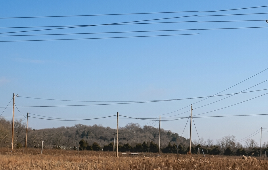
"K0UO, Miles of WIRE, in the AIR, and ON the AIR daily"
At the K0UO rhombic farm and antenna test range, the world’s largest facility dedicated to advanced antenna design and testing, engineers push the boundaries of what’s possible. We don’t just guess antenna gain - we measure it meticulously, ensuring every antenna performs at its peak.
The K0UO site, proudly uses repurposed equipment from W6AM's old station, W7YRV, Voice of America, DOD, The BBC, and other legendary stations on the K0UO large arrays.
"I hope others will carry on the tradition, and art of building the large Rhombic Arrays in the future". It is truly the "PHD" of wire antennas.

To be effective, an efficient station you must balance performance, ergonomics, and reliability.
K0UO emphasizes the scientific method: model → build → far-field test → refine
When discussing antenna performance, the practical application of these theories is crucial. For example, a Rhombic antenna, recognized for its distinctive shape and high gain features, can greatly improve the quality of transmitted and received signals. This antenna is especially useful for DX long-distance communication because of its directional properties. It can effectively manage the bandwidth of communication, enabling operators to access frequencies that might otherwise be obscured by noise.
The site emphasizes the scientific method: model → build → far-field test → refine


The Rhombic antenna's design consists of two pairs of wires that form a diamond shape, which contributes to its ability to focus energy in a specific direction. This focus not only improves signal strength but also enhances the clarity of the communication, making it a favored choice among seasoned operators who are serious about their craft. The ability of a Rhombic antenna to perform excellently in various conditions, despite what theoretical models may suggest, exemplifies the importance of practical experience and on-the-air testing.
Moreover, the performance of such antennas can be influenced by various factors including terrain, atmospheric conditions, and even the specific equipment used in conjunction with them. This is where the distinction becomes clear between those who rely solely on theoretical models and those who engage in hands-on experimentation and adjustment. The big guns, who often have the experience and knowledge to tweak their setups, can achieve remarkable results that far exceed the predictions made by software like EZNEC.
The Big Advantage, all long HF Traveling wave antennas are known for fantastic Improvements in the reduction of QSB fading, for both transmit or receive.
It is like Diversity, theses large arrays cover a lot of area. My station uses miles of wire, so you are both listening and transmitting signals coming and going at different angles. Signal-to-noise ratio (S+N/N ratio, or SNR) is one technical aspect not too many amateurs give a second thought about, however if you can't hear them you can't work them. This is very apparent on audio reception, long Traveling wave antennas eliminates much of the audio amplitude fading for both transmit or receive. The RF signal is almost never in a stable phase relationship at both places at the same time. This means the signal will have random phase and amplitude differences. The arrival angle and polarization of incoming signals will change. This generally results in the fading, by having many wavelengths of wire in the air, the chances are that while one area experiences a fade, the other will not. The power is in the diversity size of the array, and what you can now hear with out QSB fading. Traveling wave antennas are just quieter and have substantial noise reduction. That is why so many people use the Beverage receive antennas.

A Rhombic reduces E-field gradient at the high the voltage points of the antenna. It solves the problem where antenna tips or ends were charged by a transmitter with very high voltages. A similar effect occurs when receiving when the environment around the antenna is charged from inclement weather. The very high voltage gradient between the antenna and the air around the antenna causes corona discharge. Which appears as a hissing, whining, sizzling, or popping noise in the receiver. The most intense charge buildup occurs at the highest point, farthest from earth and at a point away from other objects in open space. The shape of a Rhombic minimizes protrusions, and places a blunt edge towards the highest charge gradient areas alone the antenna. An yagi or dipole element, on the other hand, has protruding points that extend well out into clear air where charge density and voltage gradient is highest.
Understand your Forward Gain
Emphasizing the concentration of energy in the direction is crucial. The gain should be consistent across a full range of frequencies and must be compared to a standard reference.
Note, this K0UO blog uses dB gain, not dBi when providing Rhombic and V Beam antenna gain data, just don't be fooled by dBi.
Comparing Rhombic Antennas to Other HF Antennas
| Antenna Type | Gain | Bandwidth | Size | Directionality | Cost |
|--------------------|---------------|-----------------|---------------|-----------------|----------------|
| Rhombic | High (12-18 dB) | Wide (3-30 MHz) | Large | Highly directional | Low |
| Dipole | Standard (2-3 dBi) | Narrow | Small | Omnidirectional | Very low |
| Yagi-Uda | Moderate (6-10 dBi) | Narrow | Medium | Directional | Moderate |
| Log-Periodic | Moderate (6-10 dBi) | Wide | Medium | Directional | Moderate |
Now days the biggest gun contest or DX stations would use a
4, over 4, over 4, stacked 40 and 20 meters Yagis at ~180 ft is very high-end (gain often ~10–13 dBd real-world, depending on phasing/spacing ~0.5–0.75λ vertical).
Nevertheless, a properly sized rhombic with 100 ft apex (long legs) can provide higher forward gain (3–5 dB more in modeled comparisons at low angles), significantly improved F/B, and multi-band capability. By utilizing a K0UO 90% efficiency re-phasing system, you can achieve even greater gain, without the need for moving towers to adjust or parts that might fail. An additional advantage is the diversity in TX & RX, which helps reduce QSB fading.
Switching speed depends on whether the movement for a beam and is mechanical, however it is electrical and instantaneous with a Rhombic array.
Rhombic Arrays (Instantaneous): Because these are typically fixed wire structures, changing direction is done through relay switching. By having multiple rhombics K0UO is pointed in 14 different fixed directions (e.g., every 25°), you can switch between them instantly—typically in milliseconds—at the press of a button or via automated software.
Stacked Yagi Beams (Slower Mechanical): To change the direction of a stacked Yagi beam, you must physically rotate the entire mast and antenna assembly using a mechanical rotor.
Rotation Time: This can take anywhere from 60 to 120+ seconds to complete a full 360° turn, depending on the rotor's speed and the antenna's mass.
Phasing Options: While you can use a relay switching system to select different combinations of antennas within a stack to adjust elevation or gain, you still have to wait for the rotors to reposition and move to a new target direction try doing this for 24 hours for a contest.
In short, a rhombic array farm provides instantaneous direction switching, while a stacked Yagi beam is constrained by the mechanical rotation speed of the antenna's mounting hardware.
So if you're considering a fixed-wire setup to eliminate rotor maintenance and require frequency flexibility, choose a Rhombic or V Beam.
Geographic Propagation Advantage of Kansas at this station: Thanks to its prime location, K0UO is perfectly positioned to excel in DX and radio contests, giving operators the chance to skyrocket their scores! Nestled in vast rural expanses with endless acres of land, the RF noise floor is practically non-existent. With neighbors miles apart, the station can pick up those faint signals that urban or suburban operators only dream of.
With arrays operating at take-off angles of 5 to 10 degrees, K0UO consistently leads the way, being the first to open and the last to close to Europe, Asia, and across the poles to Western Asia and the Middle East, while also keeping a steady connection to South America.
The K0UO site has miles of wire with incredibly high-gain "Rhombic Curtain and V Beam arrays". They truly reign supreme as the King of HF Wire Antennas, unmatched by any yagi!
Rhombic antennas offer higher gain and wider bandwidth than many common HF antennas but require more space. Yagi antennas provide good gain with smaller size but cover a much narrower frequency ranges. Dipoles are simple and small but lack directionality and gain.
• Front-to-Back Ratio (F/B) - This is the ratio of the response in the direction of maximum gain compared to the response directly behind the antenna (at 180⁰)
• Front-to-Rear Ratio (F/R) - This is the ratio of the response in the direction of maximum gain compared to any response in the hemisphere behind the antenna (from 90⁰ to 270⁰)
• Standing Wave Ratios (SWR) - An efficiency measure showing the relative size of reflections and their impact on the power of the antenna and gain, The pattern of a directive antenna changes over a frequency band
The power in the diversity of the large size of the array, and what you can now hear with out QSB fading, is even more gain on RX.
Understanding Rhombic Antennas and Their Functionality
Rhombic antennas are a fascinating type of antenna that belong to a broader category known traveling wave arrays

.
The performance of such antennas can be influenced by a multitude of factors that extend beyond mere theoretical calculations. These factors include, but are not limited to, the geographical terrain surrounding the antenna, atmospheric conditions such as humidity, temperature, and pressure, and even the specific equipment used in conjunction with the antennas themselves. For instance, the presence of mountains, tall buildings, or other obstructions can significantly affect signal propagation and reception, leading to variations in performance that are not always accounted for in theoretical models. Additionally, atmospheric phenomena, such as temperature inversions or varying humidity levels, can cause fluctuations in signal strength and clarity, further complicating the predictive accuracy of software simulations. At K0UO we are using AI which is now becoming an advanced tool in analyzing, developing, and expanding research in RF and antenna.
This is where the distinction becomes particularly clear between those who rely solely on theoretical models and those who actively engage in hands-on experimentation and adjustment. Theoretical models, while very valuable for initial designs and predictions, often cannot capture the full complexity of real-world conditions. In contrast, practitioners who take the time to experiment with their setups, making adjustments based on live feedback from their antennas, can often discover optimal configurations that significantly enhance performance. The big guns in the field—those seasoned professionals and dedicated amateurs—who possess the experience and extensive knowledge required to fine-tune their setups, can achieve remarkable results that far exceed the predictions made by software like EZNEC.
These individuals often utilize a combination of empirical testing and a deep understanding of radio wave propagation principles, allowing them to manipulate variables such as antenna height, orientation, and even the choice of feedline to maximize their signal strength and clarity. They may also employ advanced techniques such as remote monitoring and data logging to assess performance over time and under varying conditions. This iterative process of testing, analyzing, and adjusting enables them to refine their setups continuously, leading to a level of performance that is not only practical but also often astonishingly effective. As a result, the gap between theoretical predictions and real-world performance can be bridged through diligent experimentation and a commitment to understanding the traveling wave antennas operation.
These antennas are specifically designed to efficiently radiate or receive radio waves, and they exhibit unique characteristics that set them apart from other types of antennas.
The Rhombic Arrays can beat the massive stacked HF yagi beam arrays.


What is a Rhombic Antenna?
A rhombic antenna is typically constructed in the shape of a rhombus, which is a four-sided figure with equal-length sides. This geometric configuration is not merely aesthetic; it plays a crucial role in the antenna's operational efficiency. The design allows for a wide bandwidth and a relatively high gain, making rhombic antennas particularly effective for long-distance communication.
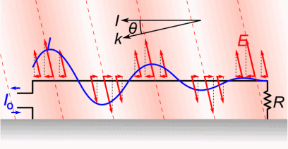
Traveling Wave Antennas Explained
The classification of rhombic antennas as traveling wave antennas indicates that they operate based on the principle of wave propagation along the antenna structure. Unlike standing wave antennas, which have fixed points of maximum and minimum voltage (standing waves), traveling wave antennas like the rhombic utilize the continuous movement of waves along the length of the antenna. This results in a more uniform radiation pattern and often leads to enhanced performance in terms of signal strength and clarity.
Operational Characteristics
One of the key operational characteristics of rhombic antennas is their ability to maintain a consistent radiation pattern over a wide frequency range. This is particularly advantageous in applications where frequency agility is required. Additionally, rhombic antennas can be designed to operate in various configurations, allowing them to be tailored for specific communication needs. Moreover, the placement and orientation of a rhombic antenna can significantly influence its performance. Typically, these antennas are installed at a height that optimizes their line-of-sight communication capabilities. The angle at which the antenna is deployed can also affect its gain and directivity, making it essential for operators to consider these factors during installation.
Applications of Rhombic Antennas
Rhombic antennas are widely used in various applications, particularly in the field of amateur radio, military communications, and broadcasting. Their ability to cover large distances makes them suitable for long-range communication systems. Furthermore, due to their relatively simple construction and low cost, they are often favored by hobbyists and researchers who require effective communication solutions without significant financial investment. In summary, rhombic antennas are a specialized type of traveling wave antenna that leverage their unique geometric design and operational principles to facilitate efficient communication over long distances. Their versatility, operational characteristics, and wide range of applications make them an important component in the field of radio telecommunications. Understanding the intricacies of how these antennas function can greatly enhance the effectiveness of communication systems that rely on them.
In conclusion, while theoretical models provide a useful framework for understanding antenna performance, it is the real-world application and the ability to adapt to changing conditions that truly defines success in the field of radio communications. A Rhombic antenna serves as a prime example of how practical experience and a willingness to experiment can lead to superior performance, showcasing the difference between the big guns and the little pistols in the world of amateur radio.
Rhombic Antennas were used in WWII Military Communications, they were harnessing the RF Power, to Win the War
In the USSR they used more large wire arrays than Beams
Grigory Zakharovich Ayzenberg (Григорий Захарович Айзенберг, 1904–1994) was a monumental figure in Soviet radio physics and the chief architect behind the USSR’s global shortwave and military antenna infrastructure.
The Prolific Author: He held 53 Soviet author certificates (patents) and published over 60 core scientific works. His definitive textbook series, including "Shortwave Antennas" (Коротковолновые антенны) and "Ultra-Shortwave Antennas" (Антенны ультракоротких волн), became the literal bibles for Soviet communications engineers.
Mastering Traveling-Wave Antennas: While Western designers focused heavily on resonant aluminum beams (like Yagis and LPDAs), Ayzenberg mastered wire arrays that leveraged traveling waves (Rhombics, V-Beams, and Fishbone arrays). He engineered the transition from single-wire systems to multi-wire "curtain" configurations to lower high-impedance loads, stabilize SWR, and widen operating bandwidths.
A Rhombic Antenna = The highest development of a long-wire antenna.
Each antenna a K0UO was built for 40 meters and above, with over 600 to 800 foot per-leg and +1200' end to end, 6 to 7 Acres each on 80 to 100 foot wood poles. My four antennas each cover an area equal to five football fields. The Front to Back is like a brick wall, maybe +40dB or more. That makes them 4 to 6 Wave-Lengths long on each of the four sides, or 16 to 24 wave-lengths total for 40 meters, these may be the largest 40 meter Rhombic antennas in current amateur use. K3LR may or may not have more gain with beams, using 4 over 4 over 4 on 40 meters, but he needs to rotate. With the four rhombic arrays and three V-beams, the K0UO antennas effectively cover 14 directions, every 25°, the beam width of each array. The Re-entrant Rhombic array is one of the highest forward gain HF antennas with its 90% efficiency, now with very high gain, and low noise receive characteristics. The Rhombic Arrays have much more gain than the massive stacked HF yagi beam arrays, that I had up previously.
The secret not showed in modeling programs
Do not underestimate the performance of the Rhombic antenna unless you have personally constructed and utilized one. Due to their substantial size, spanning many acres, Rhombic antennas offer a significant advantage with thousands of feet of wire elevated in the air. This configuration creates signal diversity by capturing signals at various times and angles, significantly reducing fading (QSB) and effectively transmitting RF signals. Unlike stack beams, Rhombic antennas provide a diversity gain that cannot be replicated in models, often reaching as high as +6 dB. This gain can be crucial for successfully receiving and transmitting DX signals. The military and shortwave broadcasters have recognized and leveraged this advantage for decades.
Don't underestimate the performance of the Rhombics; to truly grasp its capabilities, you need to construct and use one on the air yourself, rather than merely analyzing models.
It is crucial to recognize that a significant majority of HF amateur radio Yagi beam antennas, along with a substantial portion of commercially available HF beam antennas, have not undergone any rigorous testing, on established antenna test ranges in contemporary times.
This lack of standardized testing means that many users may not have access to reliable performance data, which can lead to misconceptions about the capabilities and efficiencies of these antennas. Without proper testing, it becomes challenging for amateur radio operators to make informed decisions based on the advertised specifications and performance metrics provided by manufacturers.
In contrast, many VHF and higher band antennas have benefited from some level of informal testing, primarily due to the efforts of dedicated organizations such as The Central States VHF Society and the Microwave Update group. These organizations play a pivotal role in the amateur radio community by annually organizing conferences where they establish temporary test ranges. During these events, participants can conduct hands-on evaluations of various antennas, allowing for comparative analysis and performance assessments. Such testing is invaluable as it not only provides real-world data but also brings to light deficiencies in certain models and the claims made by some manufacturers. Through these informal tests, operators can gain insights into which antennas perform well and which do not, ultimately guiding their purchasing decisions.
However, despite the progress made in the VHF and higher frequency bands, there remains a glaring void when it comes to comprehensive far-field testing for HF antennas, including both wire-based designs and high-performance Yagi beam antennas. The absence of rigorous testing protocols means that users are often left to rely on anecdotal evidence or unverified claims regarding the performance of these antennas. Consequently, much of the documentation provided by manufacturers can be quite misleading, presenting specifications that may not reflect actual performance in real-world scenarios. This situation emphasizes the necessity for more structured testing environments and standards for HF antennas, which would not only enhance the credibility of manufacturers' claims but also empower consumers with accurate information to make better-informed choices in their amateur radio pursuits.
Modern alternatives still can't beat the big HF Rhombic:
Using K0UO +90% re-entrant re-phasing system no power is lost by terminating resistors.
Yagis even stacked ones,( 4 over 4 over 4 at 200 feet have about the less gain)
Log-periodic antennas
Vertical phase arrays, 4 Sqs
Wire antennas with tuners
Phased dipoles
The Rhombic and V-Beam antenna array is still an excellent HF antenna for commercial, maritime shore stations, military, broadcasting, frequency agile, requirements, high speed traders, diplomatic, EME and ham amateur radio.
Based on the site other blogs content, our four 40‑meter resonant rhombic antennas at K0UO are aimed at the primary DX directions as part of the farm’s 14‑direction coverage (arrays and V‑beams every ~25°). The blog posts and site notes identify collective coverage rather than a numbered compass heading for each rhombic, but they state the system was laid out to target the eight main DX areas and that the full farm (four rhombics + three V‑beams) provides beams every ~25°. Specifics given in the material: the arrays serve NE/Europe, Africa/Mideast, Central & South America, Oceania/Asia and other DX sectors; one vertical‑polarized 1/2 rhombic is noted as firing to Central & South America.
Dick AD4U from eham.net
On the W8IJ antenna page, he presents intriguing observations regarding the modeling of the large rhombic antenna. It's important to note that he isn't particularly enthusiastic about its advantages or gain per area of antenna space used. He mentions, "The rhombic's performance is largely limited by the high levels of spurious lobes and its poor efficiency (50%), particularly over typical soil. The standard rhombic ranks among the lowest in terms of gain-per-acre for high gain HF antenna arrays."
However, K0UO now utilize a Re-entrant system that achieves 90% efficiency, by re-phasing the power back into the antenna, rather than dissipating it as heat in termination resistors.
Keep in mind that K0UO is comparing rhombics to large stacked single band beams that were previously used on 195-foot rotating towers at K0UO, and has tested both yagis and rhombics on the RSI Corp antenna test range. "Rhombics bets Beams"
It can be truthfully said, that "a Rhombic antenna occupies more space per dB of gain than any other antenna." This statement holds significant weight in the realm of antenna design and application, particularly when discussing the trade-offs between gain and physical footprint.

The Rhombic antenna is renowned for its very high-gain characteristics, making it a preferred choice for many long-distance communication applications. However, one of the major drawbacks is its requirement for extensive land area, measured in acres, which can be a limiting factor for many operators. Furthermore, when properly terminated, the efficiency of a standard Rhombic antenna is only about 50%. This means that nearly half of the power fed into the antenna is dissipated rather than radiated effectively, which is a critical consideration for maximizing the performance of a communication system. An alternative impedance-termination system that has been explored, albeit primarily in a limited number of large broadcast stations where input powers exceed 50 kW, is known as the re-entrant line termination. This innovative approach was notably developed by Clyde Haehnlen SK, who crafted the specifications for the Voice of America antenna system located at the Bethany, OH Relay Station. The re-entrant Rhombic antenna designed for this application achieved an impressive efficiency of 90%. This was accomplished by re-phasing the power rather than relying on the conventional method of dissipating excess energy through heating termination resistors. In this advanced system, the Rhombic antenna is terminated in a transmission line, which is then coupled back to the input through appropriately designed voltage-matching and phasing networks. This clever arrangement allows for the energy that would typically be lost in the dissipation line to be fed back into the antenna, resulting in significantly less than 50 percent of the energy being wasted. The old VOA Bethany site in Ohio exemplified this efficiency, achieving levels exceeding 90%. The design effectively feeds back the wasted RF energy "In-Phase," directing it back into the feeder end of the antenna. This feedback mechanism is crucial for maintaining optimal performance, particularly in scenarios where there are variations from the stubs' frequency. In such cases, it is essential that the stub is returned to ensure that the system remains balanced and efficient.
K0UO uses Re-entrant Rhombic array is one of the highest forward gain HF antennas with its 90% efficiency,one of the highest forward gain of any HF ham antenna.
The K0UO station is the only station using re-entrant line termination equipment, which is re-phasing the power instead of heating up termination resistors. These antennas are now recognized as the largest wire antennas in the world. This unique position allows me to leverage the advanced design principles pioneered by Clyde Haehnlen, which have proven to be invaluable in maximizing the efficiency and effectiveness of my transmission capabilities. The implementation of this re-entrant line termination technology not only enhances the performance of my antennas but also sets a new standard in the field of antenna design and broadcasting.
Clyde provided me with invaluable design information for re-phasing a few years ago before his passing. His insights into the intricacies of antenna design and efficiency optimization continue to influence my work and inspire new innovations in the field. The legacy of his contributions lives on through the advancements made in antenna technology, particularly in the realm of high-efficiency systems like the one I am currently operating. As I continue to explore and expand upon these ideas, I remain committed to pushing the boundaries of what is possible in antenna design and communication technology.

A rhombic antenna offers the unique benefit of operating across very wide frequency ranges with consistent SWR and high gain, which a basic mono-band yagi cannot achieve. The rhombic is also a straightforward antenna, needing only four supports (three supports for the Vee beam and one support for inverted Vee variations). My antennas use 3/8" Triple Galvanized Wire Rope Cable used for the antenna wire.
The Rhombic arrays features can be highly advantageous for everyday use in amateur radio service, as amateurs are not point-to-point shortwave broadcasters, military, HF Stock Traders, or wire news services. Amateurs simply want to make QSOs! Additionally, most amateur radio operators don't have the budget for expensive tall towers and stacked mono-band beams, nor the capability to climb and maintain such structures.
NOTE, Don't underestimate the performance of the Rhombic, unless you have personally built and used one. Because of their excessive size (area) covering many acres, you see their real advantage of thousands of feet of wire in the air, which creates receive signal diversity, by capturing signals at different times and different angles, vastly eliminating fading QSB, and firing out the transmitted RF in the same way. Traveling wave antennas are very unique and unlike many other antenna in common use, and modeling will not show this major advantage.
Others using the King of antennas, In the late 1940s to 1970s W6AM had many 1000 footers and one was 1500 ft (in fact the main E/W is using parts from W6AM's farm). TF4M put up a larger one at one time, and Roy W7YRV/SK had nine at one time and he developed the X Rhombic, which he had one for every 20 degrees. That was a truly remarkable accomplishment for an amateur station (You must see his page, great info w7yrv.blogspot.com/2013/). It was an extreme pleasure for K0UO to meet Roy, even in his 90's, he was still an encyclopedia of knowledge when it comes to very high gain antennas. K0UO is very privileged that W7YRV has entrusted him with the schematics, drawing, and photos of these fabulous antennas. W1VDE Roger in OR has six and is on the air daily, also VK3MO, ZL6QH, and in Texas N5APR and W5BY Jeff, had a few at their ranch's, KL7KK in AK has one along with a few VK's, and V55V (V55W) in Namibia had 2, but they are now down.
VK3MO Ian also has a stacked rhombic antenna with 8 wavelengths on a leg giving a total of 1340m of radiating wire. The upper rhombic is at 40M and the lower rhombic is at 21M. The rhombic had a gain of 23dBi at a take off angle of 5 degrees on 20M and is directed at New York. The rhombic was modeled using EZNEC and it has 3dB more gain than the 5/5/5/5 yagis. Both the yagis and the rhombic have a take off angle of 5 degrees which allows a comparison between the two antennas in the direction of New York. Ian sees see the 3 dB advantage which validates the accuracy using NEC antenna modelling software.

While W1AW eventually replaced the massive multi-acre wire array with a stack of aluminum yagis beams and towers in the 1980s, these original 1930s QST field maps documented a legendary domestic signal that many operators noted was never fully replicated by modern directional Yagis. You can view or reference this exact historical diagram layout directly via your active Hams with Rhombic Blog draft under the section detailing the vintage ARRL antenna layout.

Rhombic antennas were the ultimate antenna design back in the Golden Age of Wireless. However, building one required a large tract of land and a number of tall telephone poles, because they have dimensions several times the wavelength. To most amateurs the positive thing is there are no large mono-band antennas to maintain, or rotators to fix, and rhombics allows for instantaneous direction and band switching. They normally can be installed at very low cost, if you have trees to hang them from, all that is needed is a lot of wire and time! Also the key concept with traveling-wave antennas is that there are no standing waves, which means that the current and voltage levels are the same everywhere along the antenna conductors. So the rhombic antenna does have the very distinct advantage of working over very wide frequency ranges with flat SWR and high gain.
Advantages
The structure of the antenna is quite simple and it is cost affordable.
It provides high directivity by radiating most of the power along the main axis.
It provides efficient long-distance radio communication when installed in a large space.
The offered input impedance is quite large.
The radiation pattern and input impedance remain constant for a large range of frequency.
These can be easily switched from one working frequency to another during operation.
It suits long-distance F-layer propagation due to low vertical radiation angle.
A excellent choice HF antenna for commercial, maritime shore stations, military, broadcasting, frequency agile, requirements, high speed traders, diplomatic, EME and ham amateur radio.
Re-entrant Rhombic array is one of the highest forward gain HF antennas. with its 90% efficiency
Paul Bittner, WØAIH/SK, had a four rhombic contest station
SEE @

W0AIH, How did his smaller rhombics perform?
A comprehensive analysis of these rhombics is beyond this article's scope, but Paul had Lew, K4VX, model these antennas using Paul's specifications at a height of 60 feet. Lew determined that with a length of 495 feet, a width of 206.7 feet, and a half-apex angle of 22.7°, the gain at 14.2 MHz is 18.9 dB. At 21.2 MHz, the gain is 20.8 dB. In practical use, it's suggested that the theoretical gain would be reduced by about 2 dB due to losses in the termination resistors. Lew also discovered that towers within a rhombic do not significantly affect the antennas' performance. Naturally, modeling an antenna and using these rhombics in actual contesting scenarios are two different things. Anecdotal evidence is quite positive.
Scott, NE9U, recalls being in the 20-meter shack at 4 AM and finding the band dead. He was rotating the stack (4/4/4/4 Hy-Gain 204Bs at 50 to 199 feet) and heard nothing. Just for fun, Scott switched to the European rhombic and, surprisingly, he heard an HZ (Saudi Arabia)! It was the only signal on the band. He moved the stack back to 43° and switched to it. The Saudi station was gone! He switched back to the European rhombic, and there it was at S-9. Scott worked him on the first call.
Bill, ACØW, has found that when the band is just starting to open on the East Coast and there's still some time before it opens in the Midwest, the rhombics allow him to get on the band earlier. By joining the band simultaneously with the East Coast stations, he can establish and hold a run frequency. If he waits until the stack can hear and work stations, the band is so crowded with East Coast stations that it's very challenging to find an opening and establish a run frequency.
Paul, WØAIH, has found that the African rhombic works very well into Oceania (VK/ZL) when he reverses its direction. He dreams of a 160-meter rhombic aimed at Europe, but he also realizes that even his 120 acres do not provide enough room to fit the necessary 2000-foot legs. On 160 meters, Paul sometimes listens on the rhombics, which are very quiet (his transmitting antenna is a vertical array). He simply switches to the rhombic that "hears" the best; typically, it's the one pointed in the direction of the station he's working. Paul says, "My personal favorite is the JA rhombic on 20 meters. I typically use the stack, mentioned above, for most of the morning and into mid-afternoon. The first time I hear or work a station in Japan, however, I immediately request the JA rhombic and start calling 'CQ.' Almost every time, this leads to a long and productive JA run."

TO SEE the complete Blog list check @ https://www.k0uo.com/k0uo
Discover the incredible expanse of Steven Walz's vast acre, home to the world's largest antenna site and test range, the K0UO ham radio station K0UO!
Explore miles of antennas dedicated to ham radio, featuring dozens of towering antenna support structures, including FCC-registered towers soaring up to 195 feet, numerous 100-foot wooden powerline poles, impressive concrete silos, and versatile portable mobile towers!
WA7ARK recommends NEC5 (newer MOM algorithm) from Lawerence Livermore Labs greatly adds to modeling capability (adds buried conductors) and makes it much easier to write models (many less restrictions compared to NEC2d)
The K0UO antenna test range site makes use of the 4KS Walz airport and its surrounding area as a practical learning environment for STEM (Scientific, Technical, Engineering, & Mathematics) antenna projects in a real-world outdoor setting. If your group has a University aerospace or antenna research STEM program, please let me know. We are using AI which is now becoming an advanced tool in analyzing, developing, and expanding research in RF and antennas.
The KØUO Rhombic Antenna Farm and Test Range: Home to the World's Largest amateur radio (ham), High Frequency (HF) Wire Antennas.
The KØUO Rhombic Antenna Farm in Kansas, consisting of many acres, with "Miles of Wire in the Air & On the Air". Best known as an antenna Experimenter, Ragchewer 1st and DXer for fun! "It takes years of Passion, Hard work, and Commitment to build a great station".


The Best Antenna is one that is "In the Air and On the Air"! As any good antenna experimenter knows, the more antennas the better, that way you can test and see how they are really working. You won't know you have a good antenna if you can't compare it with others!
K0UO has years of expertise in contesting, DXing, using cutting-edge engineering and technology. and in now using AI.
Key ways AI is enhancing amateur radio include:
Signal Processing & Noise Reduction: AI is used to clean up audio in real-time, such as the FreeDV-RADE project, which utilizes Machine Learning for noise reduction.
Antenna & Station Automation: AI tools can automatically adjust antenna tuners as frequencies change and analyze antenna performance.
Band Management & Contesting: AI monitors band activity in real-time to recommend the best frequencies, which is especially useful during contests to minimize interference.
Predictive Maintenance: AI, combined with drones, is being explored for antenna tower inspections, such as checking for cable damage.
Station Integration: AI is used to control radio operations via voice commands ("AI-enabled radio") and for automated station logging
K0OU uses many very high-gain directional LPDA-Yagis beamed at all continents, large 160 -40 meters four square verticals, stacked systems of rhombics, V-beams, and curtain arrays, The achieved goal has been met to have a world class station with multiple antennas combined (stacked) for increased gain and better performance on all the amateur bands, that are optimized for maximum gain. All utilizing optimum take off angles.


For all the other Blogs see https://www.k0uo.com/k0uo
TIP: It is a Blog, so just SKIP the Blogs HEADER and go right down to the blog.
"The K0UO station is unlike any other ham station globally," a statement that captures the essence of this extraordinary facility and its remarkable capabilities. This station stands out as a true gem in the realm of amateur radio, particularly as a Big Gun Mega Station, renowned for its impressive infrastructure and technological advancements. One of the defining features of K0UO is its ability to construct and effectively utilize the very large Rhombic and V Beams, which are specialized antenna designs known for their exceptional performance in long-distance communication. These antennas are not only complex in their construction but also require significant space and careful engineering to optimize their functionality. In addition to the Rhombic and V Beams, K0UO has a diverse array of other antennas, each selected for its unique advantages and capabilities. This variety allows the station to adapt to different frequencies and propagation conditions, ensuring that operators can maintain clear and reliable communications across a wide spectrum of amateur radio bands. The strategic placement and design of these antennas contribute to the station's ability to achieve remarkable signal strength and clarity, making it a preferred choice for serious radio enthusiasts and competitive operators alike. Moreover, K0UO is distinguished by its status as the home of the largest HF wire antennas in the world that remain operational. This impressive feat underscores the station's commitment to pushing the boundaries of amateur radio technology and its dedication to maintaining a high standard of excellence in operations. The sheer scale of these antennas not only enhances their performance but also serves as a testament to the ingenuity and passion of those who designed and built them. As a result, K0UO has become a beacon for ham radio operators, drawing interest from enthusiasts and professionals who seek to learn from its innovative approaches and unparalleled capabilities.
In summary, K0UO station is not just another Mega Big Gun ham station; it represents the pinnacle of amateur radio engineering and operational excellence. Its unique combination of advanced antenna systems, including the Rhombic and V Beams, along with the largest operational HF wire antennas, sets it apart from any other station in the world. This extraordinary facility continues to inspire and influence the ham radio community, showcasing what is possible when creativity and technical skill come together in the pursuit of effective communication.
SEE ALL BLOGS Here, & Just Skip the first few pages, and go to the Blog List
Remote operation users
Note to contest operators, DXers, and others who have made arrangements to utilize the K0UO facility: you must first sign a non-disclosure agreement and adhere to the terms prohibiting the disclosure of the "exact location" of the K0UO site you are using. Currently, the site hosts several commercial DoD/DoW projects utilizing specific HF high-gain antennas. These projects take precedence, and you will be informed if an antenna is unavailable at certain times. There are no exceptions to this rule, as agreed upon in the original agreement, which states that certain antennas are not guaranteed and may change without notice. This is in accordance with the Department of Defense utilization clause of the site (30 days on most current agreements).
The owner of the K0UO location receives hundreds of inquiries annually regarding remote use of the station for DX, casual amateur radio use, or extensive contests, including multi-multi operations. K0UO aims to be inclusive, but due to the limited number of operators that can access the facility simultaneously, a standard protocol is necessary. If you or your group have successfully negotiated an agreement, you must comply with the non-disclosure agreement. While many contests require station location disclosure, stating that the station is in Grid Square EM07, Barber County, Kansas, does not violate the agreement; only revealing the exact location or station owner/call would constitute a breach. If approved, please enjoy the station responsibly.
The facility houses tens of thousands of dollars in new Flex 8000 transceivers, amplifiers, sophisticated control and switching equipment, some of which are AI-operated, in addition to massive HF antennas such as Rhombic, V beams, Delta Loop quad-beams, four-square verticals, stacked log periodic LPDA, wire beams dipole stacked on a 195 and 100 foot towers, and a complete array of receive antennas from Beverages to loops.
The agreement you signed is confidential, prohibiting disclosure to others. This clause protects sensitive information and specific terms. Each agreement is customized to meet the unique needs of you and the owner, considering the relationship, objectives, and relevant provisions. Adhering to these guidelines fosters trust and open communication while safeguarding interests. Breaching confidentiality can lead to legal repercussions and loss of trust, so it is crucial to respect and uphold the agreement's terms.


It is great that Steve has put all this info together