


"Diversity Receive" is used 100% of the time at K0UO
- skylarkcolo

- Oct 29, 2022
- 21 min read
Updated: 1 day ago

Not needed, but I also use a Linrad program, so by attaching separate antennas to the antenna ports in the Tracking receive mode, you have true "Diversity Receive". It is a fantastic Improvement in reduction of QSB/fading. If one antenna is experiencing a deep fade, it is likely that another has a sufficient signal. Pattern diversity consists of two or more co-located antennas with different radiation patterns. This type of diversity makes use of directional antennas that are physically separated by some distance. Spatial diversity employs multiple antennas, usually with the same characteristics, that are physically separated from one another. Phase Synchronous Diversity Reception uses two widely spaced antennas (500 to 1500+ feet) feeding two identical high performance SDR receivers. Depending upon the expected incidence of the incoming signal, on the order of a many wavelengths. Collectively they are capable of discriminating a large portion of angle space and can provide a higher gain versus a single omni-directional radiator. This is absolutely a major Improvement, with Diversity Receive. My station uses over a mile of wire, listening to signals coming in at different angles. Signal-to-noise ratio (S+N/N ratio, or SNR) is one technical aspect not too many amateurs give a second thought about, however if you can't hear them you can't work them. This is very apparent on audio reception, Diversity eliminates much of the audio amplitude fading. The RF signal is almost never in a stable phase relationship at both places at the same time. This means the signal will have random phase and amplitude differences. The arrival angle and polarization of incoming signals will change. This generally results in the fading, by having two antennas, the chances are that while one experiences a fade, the other will not. The power is in the diversity and what you can now hear, with out QSB fading.
Stereo reception
Is not true diversity, where our brains can confidently interpret signals, allowing us to distinguish coherent tones from random noise. Utilizing stereo reception with two widely spaced, very quiet antennas smooths out the background noise, giving it a more "hollow" sound. This technique makes the coherent signal stand out from the noise, even as the phase rotates, just ask any good CW operator.
Old amateur operators really never die.
They just fad away (QSB)
THE BIG PROJECT STARTING SPRING 2026
K0UO's Major Initiative for 2026 is collaborating with a Department of Defense group, utilizing the Flex ML-9600X/FPA-5K and FPA-10K (not affiliated with Flex Corp) for diversity in transmission and reception, utilizing an AI platform with real time data from many SDRs.
Also some antennas on site are currently assisting a group with a project using TDoA (Time Difference of Arrival ) Direction Finding (DF) checking integrated statistical localization algorithm which allows the localization of HF transmitters based on AoA (Angle of Arrival).
K0UO is also using Transmit Diversity, for more info see the blog link below at the end of this blog.

Ongoing Scientific Research Projects
K0UO is uniquely positioned in an RF-quiet environment, allowing for the collection of raw data related to the interaction between the Sun and the ionosphere, as well as other aspects of our geophysical environment. This raw data, which encompasses noise data from these interactions and measurements of signal levels, contributes to a substantial dataset. This dataset is instrumental in enhancing our understanding of the enigmatic effects that the Sun and our space environment exert on our planet, both now and in the future.
Icom did it right on the IC 7610 and IC 7760.
Two separate DIGI-SEL preselectors, two separate Band Pass Filter networks, feed two separate A/D converters into the FPGA, not just two Receivers. You need 2 ADCs for diversity reception.
I feel the most bang for your buck, time, and enjoyment, is to get a standalone radio, built with diversity features. Not just two receivers.
Moving forward AI will be incredible tool for diversity RX.
NOTE Icom's IC 7760 sampling method, is called the Direct Sampling Superheterodyne method, at the bottom of this blog you should read the Icom Tec-report which outlines this in detail.
The IC7610 has synchronized ADCs using a single clock and customized VCXO used with the Master Clock for phase synchronous streams.
The 7610/7760 has an input for a 10 MHz reference signal for higher precision.
Direct Sampling means incoming RF signals are digitized by the Analog-to-Digital Converter and immediately processed by the FPGA (Field-Programmable Gate Array). This process greatly reduces distortion that naturally occurs in the various mixer stages found in traditional superhetrodyne receivers.
RF Direct Sampling System in the IC-7610 is capable of 110 dB RMDR, and the new IC7760 is even better. This performance gives you the ability to pull weak signals out of the noise of strong adjacent signals.
The DIGI-SEL preselectors are RF filters with sharp, narrow passband characteristics preventing Analog-to-Digital Converter overflow from large out-of-band signals when sampling the RF signals. Additionally the third and higher order IMD components are reduced. This is ideal when strong signals are received in a contest pile-up or from broadcast stations on adjacent frequencies or bands.
The IC-7610/7760 can output I/Q signals to a connected PC. Using the I/Q signals on the HDSDR (freeware), you can listen to received signals, or observe the spectrum scope on the PC to be used in combination with the LinRad software.
A few years ago I was very honored to have been personally invited by Icom's American President Hiro Nakaoka, to meet with him and key staff members, at their WA office to discuss a mutually interesting project. Later several key Icom executives also visited my office in Kansas.

SmartDiversity™ is an improvement on basic antenna phase switching by using a microprocessor controlled algorithm to determine optimum timing for the switching activity. The algorithm analyzes both the incoming RF level and the rate of change in RF level to determine the optimum timing for phase switching, and the optimum antenna phase.
K0UO is now also using Flex8600's which have true Diversity and remote .
Flex offers the most seamless remote operating experience, featuring an integrated panadapter, low-latency audio, and comprehensive radio control. SmartLink, FlexRadio's cloud-assisted remote connection service, eases NAT traversal. the 8600 Flex can even switch to synchronous diversity reception when needed, the 115db RMDR is great and with SmartSDR.
K0UO uses the Linrad program which has routines to correct amplitude and phase for complex input signals These routines operate in the frequency domain and can absorb frequency dependent phase and amplitude errors that are introduced by differences in amplifiers and filters used between the I/Q mixers and the audio board. The only requirement is that amplitude and phase errors are independent of amplitude, time and temperature.
Linrad together with hardware that can bring RF signals into digital form, Linrad forms an SDR receiver (A Software Defined Radio receiver). There is also a transmit part inside Linrad that will form an SDR transmitter together with appropriate hardware. see http://sm5bsz.com/linuxdsp/videos.htm
You can also do Diversity Receiption by using the THETIS software on many SDR radios
BELOW Apache Labs Anan 7000DLE Mk3 Diversity Reception Setup
Apache Labs Anan G2 Diversity Reception Walkthrough a must see,
BLOW: Enhanced Signal Clarity (ESC) feature of the KE9NS PowerSDR software, but not true Diversity.
MORE NOTES
The Icoms, FlexRadio, Anan, and supposedly even the K3/K4 have dual diversity processing and tracking not just dual receivers, a big difference.
I have played with the Flex and Anan, if you have a lot of time with software you can probably actually do more, but it can be complicated too.
With any of those radios you can use external computers and processing programs, as I've noted in my blog above, AI will be incredible tool for diversity RX.
I use diversity 100% the time, however now I keep it simple. So I let the radio do the work internally, and I listen to the results on one speaker. Once you've proven to yourself that it's working and is a truly valuable Aid, keep it simple.
My goal NOW is not to be constantly looking at the different signal strengths, and fiddling with software.
To prove diversity is going to work for you, you will want to listen and look at the individual receivers to start, which is interesting, and even listening on individual stereo headphones or two speakers.
Once you've seen/heard it in action, on signals with lots of QSB fading, you'll be satisfied that diversity is available tool.
For very strong signals where fading is not a problem, the diversity may not be a real advantage. However when I'm in a QSO with a strong station, I'm still using diversity. A lot of times a second or third party will join with a much different signal and distance from me. So it's just an automatic thing, in my operating practice now to always use it.
To me, fiddling with software is more of a distraction. Sometimes you may be missing a contact while you're playing with the software and computers.
I feel the most bang for your buck, time, and enjoyment, is to get a standalone radio, built with diversity features. Not just two receivers.
If you really big into software and want to spend a lot of time, then there are many options. And I know other developers are coming up with more software possibilities.
I'm very happy using the IC7610 or 7760, and keep it simple. They track and mix correctly, and are very stable.
Get up some very good antennas. Some people believe that you need a vertical or horizontal antenna and that's satisfies for diversity. The RF signals are coming in at different angles from the F layer at different times and distances. You want to capture all those signals, so the more distance between your antennas and capture area will have a big effect.
You could even to start, just combine your existing antenna with a loop, dipole, end feed, or vertical antenna, and you will see big differences, at different times of the day on different frequencies.

MY SETUP
I always use one of my Rhombic antennas, and I will either use a dipole, a beverage antenna, or one of my LPDA logs beams. On the lower bands the Beverage antennas are always the go-to.

Note
Don't use an antenna that has a lot of noise if you can help it. That's where the end feed and some verticals well hinder your results. True, some people use diversity to get rid of noise in their system, but they're really not getting the reduction in fading benefit, they're just fighting noise.
If you can definitely spread out your antennas, and if you can put up a second good antenna, they do not have to be identical in any way.
Your second receive antenna does not even have low swr.
At least now amateur radio operators have a choice in radios and software. In the past I have been at some sophisticated diversity DOD setups, using monster computers and antenna setups. Now amateur radios can do it with off The Shield equipment.
Dynamic Path Optimization: AI can now be used to adjust the diversity processing in real time based on ionospheric conditions, improving DXing and contest performance.

Your best bang for your buck would probably be with the 7610 and getting a good second antenna. But the sky is the limit and how much time you want to invest in software.
Using two receivers with two antennas, and the human brain/ears doing the computing, is also a simple way to start. You'll see that it actually works, the human brain is amazing.

AI noise reduction for radio receivers has emerged as a significant breakthrough in amateur radio technology, offering substantial improvements in signal clarity and reception. Here are the key developments and features of AI-based noise reduction for radio receivers:
RM Noise is a cloud-based AI noise suppression application that has gained popularity among amateur radio operators
Uses a customized AI model trained on amateur radio phone and CW traffic
Provides real-time noise reduction by sending audio to a dedicated inference server
Capable of eliminating RF, appliance, and power line noise
Can make S1 signals copy-able in S9 noise levels
Requires only a Windows computer with internet access and audio input from the radio


Hytera has implemented AI-based noise suppression in their H-Series DMR Radios and Push-to-Talk over Cellular devices:
Utilizes deep learning technologies to identify human voice and eliminate background noise
Employs machine learning models trained on 78 different noise environment datasets
Developed using over 250 test scenarios to evaluate the algorithm's effectiveness
NVIDIA Broadcast: While not specifically designed for amateur radio, it has shown potential for strong signal noise reduction1
Various AI-based audio processing apps originally designed for online meetings can be repurposed for radio signal noise reduction
AI noise reduction technology is revolutionizing amateur radio by:
Improving weak signal reception in high-noise environments
Enhancing overall audio clarity and intelligibility
Allowing older radios to benefit from advanced noise reduction capabilities
Potentially eliminating the need for hardware-based noise reduction solutions
As this technology continues to evolve, it is expected to become more widely adopted and potentially integrated directly into radio hardware, further improving the amateur radio experience
Noise Reduction: AI noise reduction for radio receivers is also a significant breakthrough in amateur radio technology, offering substantial improvements in signal clarity and reception, and is used at the station.
Key ways AI is enhancing amateur radio include:
Signal Processing & Noise Reduction: AI is used to clean up audio in real-time, such as the FreeDV-RADE project, which utilizes Machine Learning for noise reduction.
Antenna & Station Automation: AI tools can automatically adjust antenna tuners as frequencies change and analyze antenna performance.
Station Integration: AI is used to control radio operations via voice commands ("AI-enabled radio") and for automated station logging
Why is the IC7760 different from other radios, including IC7851, and IC7610?
The user needs to understand this in order to get the full benefits
from the radio, also when testing the RX, this must be considered (Different from other radios).
Icom uses a superheterodyne system with direct sampling
instead of direct conversion. Icom now calls it "Direct Sampling Superheterodyne", for the IC 7760
First the BPF in the RF stage that was divided into 13 parts in the IC-7850/IC-7851 and IC-7610 is further subdivided into 15 parts in the IC-7760. In the HF band in particular, the BPF is subdivided into 11 divisions instead of 9 divisions.
At the same time, the cutoff frequency of each filter has been redesigned to reduce the influence of signals on the band and in the international broadcast bands, as well as adjacent bands on the amateur band signals.
NEW
In conventional DIGI-SEL-equipped radios, the preamplifier could not be used when DIGI-SEL was in use. This is because: ߩ DIGI-SEL should be placed closer to the antenna connector than to the BPF, as it is necessary to eliminate unwanted signals as close to the antenna as possible in order to suppress distortion signal generated by non-linear components, such as switching diodes in the BPF.ߩThe preamplifier is inevitably placed after the DIGI- SEL circuit since it was always considered a matter of course to prevent unwanted frequency signals from being input into the preamplifier.
Operating the preamplifier in this arrangement would also amplify the noise component generated by the DIGI- SEL-derived gain compensation amplifier. This will not improve reception sensitivity, even though the gain is increased, so the preamplifier was forcibly turned OFF when DIGI-SEL was used in conventional radios.
Therefore, Icom re-examined whether it was really possible to place DIGI-SEL in the rear stage of the preamplifier and determined that the required sensitivity can be obtained.
So,the big win on the IC7760, is that the DIGI-SEL can be placed either in the front or rear stage of the preamplifier via a switching circuit. This switching circuit allows the user to select the appropriate setting according to the operational situation.
The users also needs to know this when testing or comparing the IC-7760 with other radios.
In the IC-7760, the DIGI-SEL unit that operates in conjunction with the operating frequency in the amateur bands from 1.8 to 28 MHz is installed in the front stage of the BPF for the Main band and the Sub band. The connection point between the BPF and the preamplifier can be switched in the latter stage, so that the preamplifier is enabled even when DIGI-SELis turned ON.
The Digital Selector circuit has a sharp peak characteristic to eliminate as many of the unwanted signals as possible and operates as a pre-selector for the operating frequency. This attenuates strong signals adjacent to the target signal and suppresses the generation of third-order distortion caused by those signals. In exchange for this sharp peak characteristic, there is a slight insertion loss, but this loss is compensated for by placing a post-amplifier immediately after the filter. This post-amplifier is a high dynamic range design with minimal gain and current feedback, so that the receiver’s strong input characteristics are not affected by this amplifier.
Icom's IC 7760 sampling method, is called the Direct Sampling Superheterodyne method.
We often hear of direct conversion methods in telecommunications equipment. Although the name “direct conversion” is similar, they are different. Direct conversion is a method in which the desired RF signal is converted to 0 Hz IF, or low frequency, before demodulation
and other processes are performed. Actually, there is no frequency called 0 Hz. In other words, 0 Hz can be regarded as direct current (DC). The RF signal is converted directly into an audio frequency, so it is called a direct conversion method. This technique can be configured using analog circuits, but it requires injecting the same frequency component as the received frequency into the mixer as a Local Oscillator (LO) signal, making it difficult to filter out the LO component leaking from the mixer.
For this reason, only a small percentage of commercially available communication devices used direct conversion with analog circuits.
A/D conversion of an RF signal requires a high-speed A/D converter that can sample at a frequency more than twice that of the RF signal to be converted. This is stated in the sampling theorem. The upper limit of frequencies that can be operated with the IC- 7760 is 60 MHz, so in order to sample RF signal, an A/D converter capable of sampling at 120 MHz or higher is required. Therefore, the IC-7760’s A/D converter uses a device capable of sampling at 130 MHz.
In the direct sampling method of the IC-7760, there are essentially no nonlinear circuits in the receiving section after the A/D converter. The analog circuits between the antenna and the A/D converter are important factors in the reception distortion characteristics of the unit. Therefore, distortion generation in these analog circuits is kept as low as possible.
Also, the signals coming from the antenna have various levels, and the dynamic range of those levels is quite large.
Those signals will be input to the A/D converter as a sum of power, so even if each individual radio signal is below the allowable level of the A/D converter, the mixing of many radio signals can cause the input level of the A/D converter to exceed the allowable level. To eliminate this condition, filter and attenuator circuits are incorporated.
The IC7760 has independent 3, 6, 12, and 24 dB attenuators that can be turned
ON and OFF by relays, and by combining these attenuators, the attenuation can be set from 3 to 45 dB in 3 dB steps.
The IC7760 uses switching with a relay, which eliminates distortion and minimizes loss when the attenuator is turned OFF. This is especially useful for removing very strong interference that cannot be eliminated by a BPF or DIGI-SEL circuit alone.
The RF signal input from the IC7760 antenna is routed to the BPF via the antenna connector switching circuit, the splitter circuit for splitting the received RF signal during Dualwatch®, one of four levels of attenuation (3/6/12/24 dB if selected). The signal continues via the HPF for removing strong mid-wave strong signals during HF band reception, and via the DIGI-SEL circuit, a narrow band variable BPF, which leads to the BPF.
The fact that the IC7760 uses Mechanical relays for all switching described above.
This eliminates distortion caused by semiconductor switching circuits, and at the same time enables reception with minimal loss, even at very very weak signal levels.
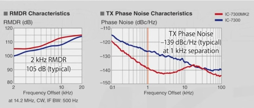
IC7851 and FTDX 101MP users, when setting up or testing the IC7760 as above, will see a noticeable improvement. When will Rob Sherwood and the ARRL Lab read this info before they test? The updated Icom design SDR architecture now used in the new 7300 has announced, that the 2-kHz RMDR of the 7300MkII will be 105 dB.
RMDR (Radio Maximum Dynamic Range) in SDR radio receivers significantly impacts performance by optimizing the dynamic range of the receiver.
NOTE UPDATE Aug 2025, RMDR is not used on Sherwood list yet, but Flex and Icom recommends it as the benchmark for testing their radios. Rob did state this on the Icom forum last week to clarify how to really read his list, "Please let me clarify how the Sherwood list is sorted/ranked. There are 158 radios listed, and they are sorted in order only by the 2-kHz 3rd-order dynamic range (DR3). All the other 13 columns have data on other performance criteria such as noise floor, sensitivity, blocking and LO Noise/RMDR, etc. (Note: There isn’t a column heading for RMDR since that definition was only defined in 2012, while the earliest radios on the list go back 50 years to 1976.)"
So as some of us know, being number one on the list, doesn't mean it is the number one overall best radio, as Rob clarifieds.https://www.youtube.com/watch?v=PeWRNij9YjM
In Software-Defined Radio (SDR), maximizing dynamic range is crucial for performance, as it enables the radio to tune across a wide swath of spectrum and accurately pick out faint signals even when strong ones are present.
Rob Sherwood had to choose one measurement for ranking the receivers.
In the days before SDR radios, all radios used PTO VFO's and crystal oscilators, so phase noise was not a problem. Thus, DR3 was a fairly good measurement of a radio's overall performance.
With todays SDR radios, phase noise is an important factor, but so are other things such as clock speeds and IP dither algorythms.
BOTTOM LINE: In order to gain a better understanding of each of the radio's ultimate performance, it is important to read the notes at the end of each of Rob's Full Reviews. Rob has used most of today's transceivers in major contests and with nearly 50 years of contest experience, can judge how well a radio performs under adverse real-life conditions.
FOR ALL ICOM 7760 users this is a must read, a Tec review for the IC7760, the RX is not the same as the IC7851, 7610 or 7300
Apache Labs Anan G2
Rob Sherwood TX/RX List overview
AI Filtering in use at K0UO
The average ham with high noise levels, will be the ones that really benefit in many aspects of using AI, it is DSP on steroids!
RM Noise is an AI noise removal client that has historically been used to significantly clean up audio from standard HF rigs. However, it can also be used with KiwiSDR, or any online SDR for that matter, by rerouting the audio output in Windows
There is a stand alone option if you can code.
RM noise is an open source AI/ML noise reduction filter available as source code on GitHub:
No internet connection needed to run it.
TO SEE the complete Blog list check @ https://www.k0uo.com/k0uo
The K0UO antenna test range site makes use of the 4KS Walz airport and its surrounding area as a practical learning environment for STEM (Scientific, Technical, Engineering, & Mathematics) antenna projects in a real-world outdoor setting. If your group has a university aerospace or antenna research STEM program, please let me know.
The KØUO Rhombic Antenna Farm and Antenna Test Range: Home to the World's Largest amateur radio (ham), High Frequency (HF) Wire Arrays, miles of wire in the air and on the air daily.
73 from,
The K0UO " Rhombic Antenna Farm" miles of wire in the Air & On the AIR daily
RMDR (Radio Maximum Dynamic Range) in SDR radio receivers significantly impacts performance by optimizing the dynamic range of the receiver.
RMDR - Which is exactly what Flex, Anan, and Icom says should be used to measure SDR receive specifications.
Note, RMDR is not used on Sherwood list yet, but Flex and Icom recommends it as the benchmark for testing their radios. Rob did state this on the Icom forum to clarify how to really read his list, "Please let me clarify how the Sherwood list is sorted/ranked. There are +158 radios listed, and they are sorted in order only by the 2-kHz 3rd-order dynamic range (DR3). All the other 13 columns have data on other performance criteria such as noise floor, sensitivity, blocking and LO Noise/RMDR, etc. (Note: There isn’t a column heading for RMDR since that definition was only defined in 2012, while the earliest radios on the list go back 50 years to 1976.)"
So as some of us know, being number one on the list, doesn't mean it is the number one overall best radio, as Rob clarifieds.
In Software-Defined Radio (SDR), maximizing dynamic range is crucial for performance, as it enables the radio to tune across a wide swath of spectrum and accurately pick out faint signals even when strong ones are present.
To me "It's a great time to be a ham radio operator, with all the exciting advancements, Good DX "
Modern SDR manufacturers like Flex, Anan, and Icom measure receiver performance by separating fundamental oscillator phase noise from derived metrics like RMDR, which makes their data more accurate and transparent than traditional Sherwood-style reports. Phase noise (measured in dBc/Hz at specific frequency offsets) directly describes how clean the local oscillator is, and it is the dominant factor that limits close-in receive performance in SDRs. By showing phase noise curves alongside RMDR plotted across multiple offsets and narrow bandwidths, these manufacturers reveal both the cause and the effect of reciprocal mixing, rather than hiding it inside a single composite number.
Sherwood tables, while still useful for legacy superheterodyne receivers, rely on single RMDR values measured under idealized conditions that can favor certain analog architectures and roofing filters. For SDRs, this approach can be misleading because digital downconversion and DSP alter how interference behaves close to the carrier. Two radios with similar Sherwood RMDR numbers can perform very differently in real CW or contest conditions if their phase noise differs. Phase-noise-first reporting better reflects real-world operation on crowded bands, especially at 1–2 kHz spacing, making it a more honest and predictive way to evaluate modern SDR receivers.
From ICOM: The user needs to understand this in order to get the full benefits from the radio, also when testing the RX, this must be considered (Different from other radios). Icom uses a superheterodyne system with direct sampling instead of direct conversion. Icom now calls it "Direct Sampling Superheterodyne".It is an amazing and detailed description of the 7760 features and how this new radio works.IC7851, 7610 and FTDX 101MP users, when moving up to to the new 7760, setting it up, using, or testing specifications will see a noticeable improvement ICOM's7760, UPDATED LINK TO THE TEC REPORT, is now found athttps://www.icomjapan.com/api/downl...2MCUyRklDLTc3NjBfVGVjaG5pY2FsUmVwb3J0XzEucGRm
Why evaluate receiver performance with RMDR? Conventionally, receiver performance has been expressed in terms of 3rd Intercept Point (IP3). However, when receivers with superior IP3 performance are compared with each other, there is a difference in actual operation, even if their IP3 values are the same. In the course of investigating and researching this difference, we focused on RMDR, which is cited by various organizations as one of the items for evaluating reception performance. At the same time, it was widely argued that RMDR performance is more important for high-performance receivers with a certain level of IP3 performance. Therefore, in the IC-7850/IC-7851 released in 2014, we also promoted reception performance in RMDR. On the other hand, for receivers employing the RF direct sampling method, IP3 as a measure of performance does not make much sense because, as mentioned earlier, they do not have an analog mixer circuit. For these reasons, Icom has positioned RMDR as an alternative to IP3 as an indicator of reception performance.
Historic Preservation: The K0UO station diligently preserves and uses components and insulators from renowned, historic radio arrays, including those from W6AM (Don Wallace), W7YRV Roy, BBC, Voice of America (VOA), and many others.
"The K0UO station is unlike any other ham station globally," making it truly unique as a Big Gun Mega Station. It is one of the few capable of constructing and utilizing very large Rhombic and V Beams, along with a variety of other antennas and AI. K0UO features the largest operational HF wire antenna in the world.
73
K0UO


"God is always the guess operator and copilot, open hearts, open minds, open doors to anyone to join in the conversation "QSO"
See the blog below. Tip: just skip the Blogs header and go down to the blog.
Transmit Diversity
See the blog below. Tip: just skip the Blogs header and go down to the blog.
Physics of QSB fading
Remote operation users
Note to contest operators, DXers, and others who have made arrangements to utilize the K0UO facility: you must first sign a non-disclosure agreement and adhere to the terms prohibiting the disclosure of the "exact location" of the K0UO site you are using. Currently, the site hosts several commercial DOD/DOW projects utilizing specific HF high-gain antennas. These projects take precedence, and you will be informed if an antenna is unavailable at certain times. There are no exceptions to this rule, as agreed upon in the original agreement, which states that certain antennas are not guaranteed and may change without notice. This is in accordance with the Department of Defense utilization clause of the site (30 days on most current agreements).
The owner of the K0UO location receives hundreds of inquiries annually regarding remote use of the station for DX, casual amateur radio use, or extensive contests, including multi-multi operations. K0UO aims to be inclusive, but due to the limited number of operators that can access the facility simultaneously, a standard protocol is necessary. If you or your group have successfully negotiated an agreement, you must comply with the non-disclosure agreement. While many contests require station location disclosure, stating that the station is in Grid Square EM07, Barber County, Kansas, does not violate the agreement; only revealing the exact location or station owner/call would constitute a breach. If approved, please enjoy the station responsibly.
The facility houses tens of thousands of dollars in new Flex 8000 transceivers, amplifiers, sophisticated control and switching equipment, some of which are AI-operated, in addition to massive HF antennas such as Rhombic, V beams, Delta Loop quad-beams, four-square verticals, stacked log periodic LPDA, wire beams dipole stacked on a 195 ft tower, and a complete array of receive antennas from Beverages to loops.
The signed agreement is confidential, prohibiting disclosure to others. This clause protects sensitive information and terms from unauthorized access. Each agreement is customized to meet the specific needs of both parties, considering the relationship, objectives, and relevant provisions. Adhering to these guidelines fosters trust and open communication while safeguarding interests. Breaching confidentiality can result in legal repercussions and loss of trust, so it is crucial to respect and uphold the agreement's terms.


The IC7610 makes it easy