


HRS-type curtain using the X-Rhombic over 18 db of gain real gain, using a Re-entrant system which is 90% efficient by re-phasing the power back in the antenna, instead of resistors.
- skylarkcolo

- Mar 2, 2019
- 11 min read
Updated: 11 hours ago


The K0UO antenna test range site makes use of the 4KS Walz airport and its surrounding area as a practical learning environment for STEM (Scientific, Technical, Engineering, & Mathematics) antenna projects in a real-world outdoor setting. If your group has a university aerospace or antenna research STEM program, please let me know.
A project underway at the Test Range is confidently testing AI-assisted real-time propagation and antenna optimization tools from a private ionosonde radar system for the DOD.
The KØUO Rhombic Antenna Farm and Antenna Test Range: Home to the World's Largest amateur radio (ham), High Frequency (HF) Wire Arrays, miles of wire in the air and on the air daily.
Traveling wave antennas are very unique and unlike many other antenna in common use, and modeling will not show many of the major advantage.

Distributed-Feed Curtains (USIA or VOA Style): These innovative antenna systems utilize branched feeding methods to effectively distribute signals to multiple dipoles, or in specific scenarios, to configurations such as K0UO cases. This approach often incorporates the use of multiple X-rhombic antennas connected in parallel, which is a strategic design choice aimed at optimizing performance. By ensuring equal power distribution across the various elements of the antenna system, these distributed-feed curtains are capable of maintaining stable radiation patterns across a broad frequency range. This characteristic is particularly advantageous in applications where consistent signal quality is essential, such as in broadcasting and telecommunications.
Technical Advantages of Distributed-Feed Curtains
One of the primary benefits of using distributed-feed curtains is their ability to minimize signal loss and maximize efficiency. The branched feeding method allows for a more uniform current distribution among the dipoles, which helps in achieving a balanced load. This balance is crucial for maintaining the integrity of the signal and preventing distortion, which can occur when certain elements receive more power than others.
Applications in Communication Systems
Distributed-feed curtains are particularly useful in various communication systems, including both terrestrial and satellite-based applications. In terrestrial broadcasting, they can be used to cover large areas with a consistent signal strength, making them ideal for radio and television transmission. Furthermore, due to their design, these antennas can be adapted for specific frequency bands, allowing for versatility in different broadcasting scenarios.
Design Considerations
When designing a distributed-feed curtain system, several factors must be taken into account, including the spacing between dipoles, the length of the feed lines, and the overall geometry of the antenna array. These parameters can significantly influence the performance characteristics, such as gain, bandwidth, and radiation pattern. Engineers must carefully calculate these elements to ensure that the antenna meets the desired specifications for its intended application.
Geographic Propagation Advantage of Kansas using this array, with less than 5 to 10 degrees take off angles, K0UO is always the first to open to Europe, Asia and over the poles to western Asia & Mideast, and it is always open to South America.
The late Roy Callison of Bisbee, AZ, ham call W7YRV/SK had nine X Rhombics arrays, which he developed, he had one for every 20 degrees. That was a truly remarkable accomplishment for an amateur station (You must see his page, great info w7yrv.blogspot.com/2013/). It was an extreme pleasure for K0UO to meet Roy, even in his 90's, he was still an encyclopedia of knowledge when it comes to very high gain antennas. K0UO is very privileged that W7YRV has entrusted him with the schematics, drawing, and photos of these fabulous antennas.

What is HRS/USIA Array?
Most people incorrectly refer to the HRS, USIA, or Distribution fed curtains as a Sterba or Bobtail Curtain. It is essential to clarify that these terms are not interchangeable, as they represent distinct types of antenna systems with significant differences in design and functionality. A Sterba curtain, for instance, lacks even 25% of the gain that a standard HRS array can deliver, which highlights the substantial performance gap between these systems.
To further elaborate, the differences in performance and construction between broadcast curtain arrays, such as horizontally polarized Distributed Fed Curtain arrays or USIA arrays, and lower gain antennas like the Sterba curtain or Bobtail antenna, which are sometimes utilized by amateur radio operators, are quite pronounced. These differences can have a profound impact on the effectiveness of the antennas in various applications. A common misconception among RF engineers is the tendency to label a modern HRS (Horizontal Dipole with Reflector and Slewing) or Distributed-Feed VOA Curtain as a "Sterba Curtain," which is fundamentally incorrect. While both types of antennas are large, wire-rigged broadside arrays that are designed to hang vertically like curtains, their electrical architecture, physics, and feeding mechanisms are entirely different and are optimized for distinct operational characteristics.
For instance, the HRS and USIA arrays are engineered to provide enhanced directivity and gain, which are critical for effective long-distance communication and broadcasting. The design of these antennas incorporates advanced techniques that maximize their performance by utilizing specific feed systems that enhance signal strength and reduce unwanted interference. In contrast, the Sterba and Bobtail antennas, while simpler in construction, do not achieve the same levels of gain and directivity, making them less suitable for applications that require robust signal transmission over long distances.
In summary, understanding the distinctions between these types of antennas is crucial for anyone involved in radio frequency engineering or amateur radio. Recognizing that the HRS and USIA arrays offer significantly greater performance capabilities compared to Sterba and Bobtail antennas can lead to more informed decisions regarding antenna selection and deployment in various communication scenarios.
The Takeaway: Referring to a VOA-type HRS curtain as a "Sterba" is akin to labeling a contemporary active electronically scanned array (AESA) radar as a "rotary radar dish" merely because both are used to scan the sky. While Ernest Sterba also invented an ingenious series-phased loop, the VOA/HRS arrays refined parallel-phased, wideband distributed networks.

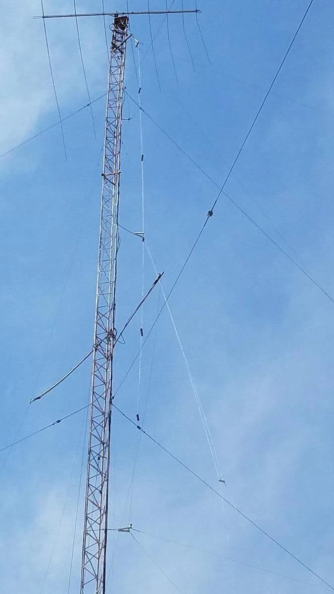
I JUST WANTED TO SAY, THANK YOU ROY. After meeting him in Jan 2019, I have been able to his X Rhombic design to build a Distributed-fed Curtain, by stacking two X-Rhombics at 190foot, and 100 foot ,and it is a steerable design. The antenna is also using Roy's old outside control_box (rebuilt) that you see in this blog. Reply. W7YRV/sk lives on, at the K0UO large antenna farm.
HRS-type curtain arrays, are sophisticated and highly effective large antennas characterized by their high gain and directional capabilities. These antennas consist of multiple horizontal wire elements (H) that are meticulously arranged to optimize signal reception and transmission. Additionally, they incorporate a wire reflector (R) that enhances their performance by reflecting signals in a specific direction. One of the most notable features of HRS-type curtain arrays is their ability to be electrically steered or "slewed" (S), which allows for dynamic adjustments to the direction of the antenna beam. This capability is particularly beneficial for adapting to varying communication needs and conditions. These high-frequency (HF) arrays are specifically engineered to produce a shallow, high-power beam that is ideal for long-distance skywave propagation, making them suitable for applications that require reliable communication over transcontinental distances. The design and functionality of these antennas enable them to effectively utilize the ionosphere for signal reflection, thereby extending their range significantly compared to traditional antennas.

Steerable (HRS): The steerable nature of these antennas is one of their most advantageous features. Slewable antennas are capable of shifting their main beam by as much as 30° in azimuth. This is achieved through the use of advanced switching delay lines, which facilitate precise adjustments in the antenna's orientation. As a result, a single fixed tower structure can effectively cover an extensive area of approximately 90° in terms of directional coverage. This flexibility is particularly valuable in situations where communication needs may change rapidly or where different geographical areas require targeted signal transmission. The ability to steer the beam enhances the antenna's effectiveness in various operational scenarios, allowing for improved signal quality and reliability across diverse communication platforms.

The K0UO pattern 30D, this is the real tested lobe at the K0UO antenna farm in Kansas. The Big Project in 2019 was a Distributed fed Curtain stacked Rhombic Steerable array (DRS) or USIA this array is for 40 meters and above with 20dB of gain.
The primary reason for selecting a curtain instead of a rhombic is to achieve a broader
beam-width along with steering, allowing coverage of a target area from side to side without using additional energy in dissipation resistance (the decision was still nearly a
toss-up) and to conserve space.

Switching, is complicated, which is introduced in the feeders at ground level to slew the beam azimuthally, or to change the radiation characteristics in the elevation plane by modifying the phase relationships. Since switching feeder line lengths in the switch-box provides control of the phase of feed to each array element, these arrays may be thought of as “phased” or “scanned.”
In the mid 20th century for point-to-point SW broadcasters would start to choose a
HRS Curtain type array to avoid side lobes, to have steering, and to use less towers (two for a curtain or 4 for a rhombic). However with rhombic now achieving up to 90% efficiency when using the K0UO multi-band re-entrant phasing system, the curtains are being challenged once more in the 21st century. K0UO incorporates the use of multiple X-rhombic antennas connected in parallel, which is a strategic design choice aimed at optimizing performance and using steering.


This antenna is fixed at 30 degrees from Kansas, but steerable, plus or minus 30° using electronic phasing, a total of 90°. The upper Array is at about 190 feet, the lower Array is at 100 feet. This antenna is designed with steerable directivity and wave angle phasing. The main area of interest for this antenna is Northern to Southern Europe, over the north pole to Western Asia, south to the Mediterranean, Northern Africa and the Mideast.
At the K0UO Rhombic Farm and RSI Corp Antenna Test Range, recognized as the world’s largest facility dedicated to advanced antenna design and testing, a team of highly skilled engineers and researchers diligently work to expand the possibilities within antenna technology. This state-of-the-art facility is equipped with cutting-edge tools and technologies that enable the exploration of new frontiers in antenna design, facilitating innovations that can significantly enhance communication systems, satellite operations, and various other applications reliant on antenna performance. We do not merely estimate antenna gain; we measure it meticulously, employing a variety of sophisticated AI techniques and methodologies, to ensure every antenna is tested under a range of conditions for optimal performance. Our measurement processes are rigorous and comprehensive, involving the use of precision instruments that capture even the most subtle variations in signal strength and quality. This dedication to accuracy ensures that we provide reliable data for critical applications, rather than mere estimates. Furthermore, our facility is designed to accommodate a wide range of antenna types, from small, compact models to large, complex systems. This versatility allows us to cater to the diverse needs of our clients, whether they require antennas for mobile communications, broadcasting, or specialized scientific research. Each test is conducted in a controlled environment, where factors such as interference and environmental conditions are meticulously managed to ensure results reflect true antenna performance. In addition to testing, our team engages in extensive research and development, exploring new materials and designs that can lead to even greater efficiency and effectiveness in antenna technology. By collaborating with academic institutions and industry leaders, we remain at the forefront of advancements in the field, ensuring that our methodologies and practices are not only current but also pioneering. Ultimately, our commitment to precision and innovation at the K0UO Rhombic Farm and Antenna Test Range positions us as a leader in the antenna testing industry, where every measurement contributes to the advancement of technology and the enhancement of communication systems globally.
Sterba or Distributed Curtain
1. The Critical Difference: Series vs. Parallel Feeding
The root of why the VOA distributed curtain destroys the Sterba comes down to how RF current is routed to the individual radiating elements.
The Sterba Curtain is Series-Fed: A Sterba is a single, continuous, long zig-zag loop of wire. The RF energy enters at one point and must travel through all the conductors in a long series path to reach the outer elements.
The Flaw: Because the wire itself has inherent resistance and a high velocity factor error, phase errors accumulate the further the energy travels from the feed point. By the time the RF current reaches the outer elements, it is slightly out of phase and weaker, causing the antenna's pristine theoretical radiation pattern to distort and its gain to drop.
The VOA Curtain is Parallel/Distributed-Fed: A distributed-feed curtain treats every single half-wave dipole element as an independent unit. A main feedline branches out into multiple, perfectly equal-length parallel transmission lines (a branching tree network) that connect to the center of every single dipole simultaneously.
The Victory: Because every element is fed from a common point via identical paths, phase error is effectively zero. All elements receive identical current and identical phase, forcing the array to hit its absolute maximum theoretical forward gain.
2. Bandwidth: The Octave Jump
Sterba Curtain: Because it relies on precise, absolute physical lengths to maintain phase relationships, it is strictly narrowband. It works on one frequency and suffers massive pattern destruction if you move even 5% away from its design center.
Distributed VOA Curtain: Because it is driven by parallel branch lines rather than series-folded loops, the elements don't "fight" each other when the frequency changes. A distributed-feed curtain can maintain a stable input impedance, maximum gain, and a clean pattern across a 2:1 frequency ratio (an entire octave). A single VOA curtain can seamlessly cover multiple shortwave bands (e.g., from 7 MHz up to 14 MHz) without sacrificing performance.
3. Electrical Beam Steering (Slewing)
Because a Sterba curtain is one hard-wired continuous loop, its directional beam is permanently fixed broadside to the wires.
A distributed-feed VOA curtain allows engineers to install delay lines or electronic phase shifters into the branching feed network. By systematically delaying the phase of the RF signal going to the left columns versus the right columns, the forward beam can be electronically steered (slewed) up to 30 degrees left or right in azimuth. Similarly, delaying upper rows relative to lower rows can adjust the elevation (takeoff angle), allowing a single fixed wire structure to target entirely different continents based on time of day.
4. Gain-per-Acre Efficiency
Because the parallel feed system forces uniform current distribution across the entire vertical aperture, a distributed-feed curtain achieves the absolute highest gain-per-acre of any antenna system ever conceived.
A standard 4-element-wide by 4-element-high distributed curtain backed by a wire reflector screen can effortlessly pull 17 to 22 dB of raw forward gain.
A Sterba curtain occupying a similar physical footprint struggles to get anywhere near that, often hitting a hard ceiling around 12 dB due to the cumulative phase and current degradation inherent in its series layout.
Conclusion
In summary, distributed-feed curtains, particularly those designed in the USIA or VOA style, represent a sophisticated solution for modern antenna systems. By leveraging branched feeding techniques and parallel configurations of dipoles or X-rhombics, these systems provide enhanced power distribution and robust performance across a wide range of frequencies. Their applications in communication technologies underscore their importance in achieving reliable and efficient signal transmission in an increasingly connected world.

SEE K0UO's CURTAIN PAGE https://www.k0uo.com/post/current-distributed-feed-system-as-used-on-sterba-curtains-will-be-utilized-on-the-new-antenna
"I hope others will carry on the tradition, and art of building the large Rhombic Arrays in the future". It is truly the "PHD" of wire antennas.
Historic Preservation: The K0UO station diligently preserves and uses components and insulators from renowned, historic radio arrays, including those from W6AM (Don Wallace), W7YRV Roy, BBC, Voice of America (VOA), and many others.
"The K0UO station is unlike any other ham station globally," making it truly unique as a Big Gun Mega Station. It is one of the few capable of constructing and utilizing very large Rhombic and V Beams, along with a variety of other antennas and AI. K0UO features the largest operational HF wire antenna in the world.
K0UO near Kiowa, KS has many types of High-Performance Antennas: Using large High Frequency HF stacked LPDA-Yagi beams, Rhombics, V Beams, Curtain arrays, Four-square phased verticals on specific bands, optimized for low noise and very efficient and high gain.
TO SEE the complete Blog list check @ https://www.k0uo.com/k0uo


Now that is a hig gain array for a ham