


Math for the Rhombic & V Beams Array
- skylarkcolo

- Apr 23, 2024
- 5 min read
Updated: May 7

The above is all the info/data that you need to build a Rhombic
The site emphasizes the scientific method: model → build → far-field test → refine


NOTE, Don't underestimate the performance of the Rhombic, unless you have personally built and used one. Because of their excessive size (area) covering many acres, you see their real advantage of thousands of feet of wire in the air, which creates receive signal diversity, by capturing signals at different times and different angles, vastly eliminating fading QSB, and firing out the transmitted RF in the same way. Traveling wave antennas are very unique and unlike many other antenna in common use, and modeling will not show this major advantage.
The site emphasizes the scientific method: model → build → far-field test → refine
I now use NEC5 (newer MOM algorithm) from Lawerence Livermore Lab, but it still won't show the real performance of the Rhombic
A word about modeling: You no longer need the latest modeling software, as it's design is rapidly evolving with Artificial Intelligence.
We started integrating AI with modeling in 2024, and now have developed an AI analysis platform focused on antenna performance and specific parameters. Be cautious and invest time in setting the correct parameters for your "AI platform".
One high end paid AI platform is now using AN-SOF, which is a robust simulation engine designed for the modeling and analysis of complex antenna systems and radiating structures.
Gain total spatial awareness of your antenna’s performance with immersive 3D rendering. AN-3D Pattern utilizes colored mesh and surface mapping to visualize radiation lobes with professional clarity.
Creating a well-designed platform using scientific and engineering knowledge is crucial.
Relying solely on ChatGPT is not the solution at all!
K0UO & RSI Corp, which employs Artificial Intelligence for designing traveling wave and other antennas, is significantly more reliable and completes the process in just 5% of the time needed by traditional modeling programs. While setting it up requires time, akin to the initial setup of the original computer modeling software, it's crucial to remember that assuming artificial intelligence operates flawlessly can lead to mistakes.
After designing, we confidently utilize our outdoor testing range to validate the results. Confirming results and assessing performance in real-world conditions is essential. Over the years, my team has effectively collaborated with numerous commercial clients to achieve this.
I started with calculators, and some of us are old enough to remember using slide rules and pencils, before moving to computer modeling. It's astonishing to see how far we've come, and in a few more years, like it or not AI will further revolutionize antenna design.
L. B. Cebik, W4RNL Model below
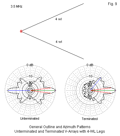


WA7ARK recommends NEC5 (newer MOM algorithm) from Lawerence Livermore Labs greatly adds to modeling capability (adds buried conductors) and makes it much easier to write models (many less restrictions compared to NEC2d)
I now model all my antennas using NEC5 and HFTA (High Frequency Terrain Analysis) to evaluate the take of angle of the various antennas over real ground, and use 3/8" Triple Galvanized Wire Rope Cable is used for the antenna wire.
Also at the K0UO rhombic farm and antenna test range, the world’s largest facility dedicated to advanced antenna design and testing, engineers push the boundaries of what’s possible. We don’t just guess antenna gain - we measure it meticulously, ensuring every antenna performs at its peak.
Today, nearly all HF amateur radio Yagi beam antennas, along with numerous commercial HF beams, remain unevaluated on antenna far-field test ranges. While VHF and higher frequency band antennas have undergone informal testing by organizations like The Central States VHF Society and Microwave Update, exposing deficiencies in some manufacturers' models and claims, there is a notable lack of real-world far-field testing for HF antennas, including wire-based and high-performance Yagi beams. Manufacturer documentation often misleads consumers.

NOTE: Do not underestimate the performance of the Rhombic unless you have personally built and used one. Despite their large size, covering many acres, their real advantage lies in having thousands of feet of wire in the air. This setup creates receive signal diversity by capturing signals at different times and angles, significantly reducing fading QSB and efficiently transmitting RF. Traveling wave antennas are unique and unlike many other commonly used antennas, and modeling does not reveal this significant advantage.
Based on the site other blogs content, our four 40‑meter resonant rhombic antennas at K0UO are aimed at the primary DX directions as part of the farm’s 14‑direction coverage (arrays and V‑beams every ~25°). The blog posts and site notes identify collective coverage rather than a numbered compass heading for each rhombic, but they state the system was laid out to target the eight main DX areas and that the full farm (four rhombics + three V‑beams) provides beams every ~25°. Specifics given in the material: the arrays serve NE/Europe, Africa/Mideast, Central & South America, Oceania/Asia and other DX sectors; one vertical‑polarized 1/2 rhombic is noted as firing to Central & South America.
The K0UO amateur ham radio antenna range, and testing site has the use of over a 1200 acres around the main antennas for far field measurements, using a portable tower or drone loaded with calibrated RF EME survey instruments (used for DOD/ Govt, Commercial and amateur radio), see the far field test page. https://www.k0uo.com/post/model-and-then-do-far-field-test
The K0UO antenna test range site makes use of the 4KS Walz airport and its surrounding area as a practical learning environment for STEM (Scientific, Technical, Engineering, & Mathematics) antenna projects in a real-world outdoor setting. If your group has a university aerospace or antenna research STEM program, please let me know. The KØUO Rhombic Antenna Farm and Antenna Test Range: Home to the World's Largest amateur radio (ham), High Frequency (HF) Wire Arrays, miles of wire in the air and on the air daily.


See the other pages on K0UO for much more design info
TO SEE the complete Blog list check @ https://www.k0uo.com/k0uo
TIP: It is a Blog, so just SKIP the Blogs HEADER and go down to the blog.
To build a 20 meter Rhombic to get 10D takeoff


Comments